Lexus RX (RX 350L, RX450h) 2016-2026 Repair Manual: Diameter of the Tire is not Uniform (C1337)
DESCRIPTION
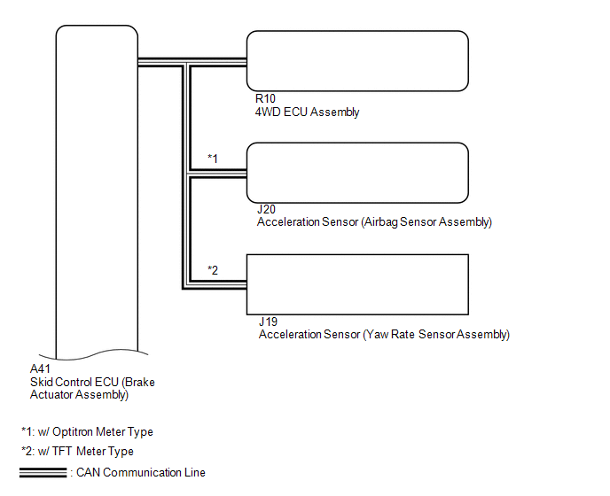
The 4WD ECU assembly stores this DTC if a difference in tire size is detected.
| DTC No. | Detection Item | DTC Detection Condition | Trouble Area |
|---|---|---|---|
| C1337 | Diameter of the Tire is not Uniform | When the following continues for 36 seconds or more: At a vehicle speed of 30 km/h (18.6 mph) or more, the average speed difference between the front wheel and rear wheel is 4% or more. |
|
WIRING DIAGRAM
CAUTION / NOTICE / HINT
NOTICE:
When the 4WD ECU assembly is replaced with a known good one from another vehicle, it is necessary to perform calibration.
Click here .gif)
HINT:
Check the condition of each related circuit connector before troubleshooting.
Click here
PROCEDURE
| 1. | CHECK TIRE CONDITION |
(a) Check the size and condition of all 4 tires.
HINT:
This DTC is output when tire deformation or a difference in tire size is detected.
OK:
The diameter and air pressure of all 4 tires are the same.
| NG | .gif) | PERFORM AIR PRESSURE ADJUSTMENT OR REPLACE TIRES SO THAT ALL 4 TIRES ARE SAME IN SIZE |
|
.gif)
| 2. | CHECK FOR DTC |
(a) Clear the DTCs.
Chassis > Four Wheel Drive > Clear DTCs(b) Start the engine.
(c) Drive the vehicle at a speed of 30 km/h (19 mph) or more so that the same DTC is output.
Chassis > Four Wheel Drive > Trouble Codes(d) Check if the speed sensor DTC (vehicle stability control system DTC) is output.
Chassis > Brake/EPB > Trouble Codes(e) Read the DTCs using the Techstream.
| Result | Proceed to |
|---|---|
| Only DTC C1377 is output (w/o AVS) | A |
| Only DTC C1377 is output (w/ AVS) | B |
| DTCs are not output | C |
| Speed sensor DTCs (vehicle stability control system DTC) are output | D |
| B | | GO TO STEP 4 |
| C | | CHECK FOR INTERMITTENT PROBLEMS |
| D | | REPAIR CIRCUIT INDICATED BY OUTPUT CODE (VEHICLE STABILITY CONTROL SYSTEM) |
|
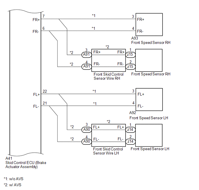
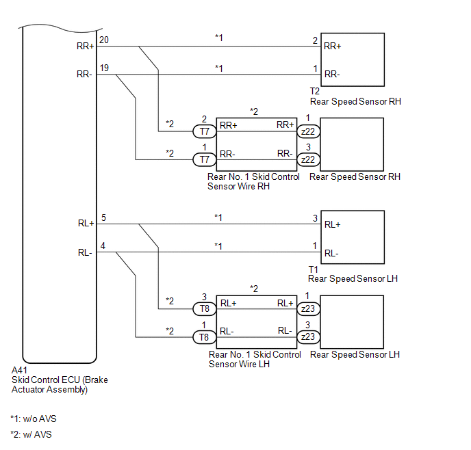
| 3. | CHECK HARNESS AND CONNECTOR (SPEED SENSOR - BRAKE ACTUATOR ASSEMBLY) |
(a) Make sure that there is no looseness at the locking part and the connecting part of the connectors.
(b) Turn the engine switch off.
(c) Disconnect the A41 skid control ECU (brake actuator assembly) connector.
(d) Disconnect the A92, A93, T1 and/or T2 speed sensor connector(s).
(e) Measure the resistance according to the value(s) in the table below.
Standard Resistance:
for Front RH:| Tester Connection | Condition | Specified Condition |
|---|---|---|
| A41-7 (FR+) - A93-3 (FR+) | Always | Below 1 Ω |
| A41-6 (FR-) - A93-4 (FR-) | Always | |
| A41-7 (FR+) or A93-3 (FR+) - Body ground and other terminals | Always | 10 kΩ or higher |
| A41-6 (FR-) or A93-4 (FR-) - Body ground and other terminals | Always |
| Tester Connection | Condition | Specified Condition |
|---|---|---|
| A41-22 (FL+) - A92-3 (FL+) | Always | Below 1 Ω |
| A41-21 (FL-) - A92-4 (FL-) | Always | |
| A41-22 (FL+) or A92-3 (FL+) - Body ground and other terminals | Always | 10 kΩ or higher |
| A41-21 (FL-) or A92-4 (FL-) - Body ground and other terminals | Always |
| Tester Connection | Condition | Specified Condition |
|---|---|---|
| A41-20 (RR+) - T2-2 (RR+) | Always | Below 1 Ω |
| A41-19 (RR-) - T2-1 (RR-) | Always | |
| A41-20 (RR+) or T2-2 (RR+) - Body ground and other terminals | Always | 10 kΩ or higher |
| A41-19 (RR-) or T2-1 (RR-) - Body ground and other terminals | Always |
| Tester Connection | Condition | Specified Condition |
|---|---|---|
| A41-5 (RL+) - T1-3 (RL+) | Always | Below 1 Ω |
| A41-4 (RL-) - T1-1 (RL-) | Always | |
| A41-5 (RL+) or T1-3 (RL+) - Body ground and other terminals | Always | 10 kΩ or higher |
| A41-4 (RL-) or T1-1 (RL-) - Body ground and other terminals | Always |
(f) Connect the A92, A93, T1 and/or T2 speed sensor connector(s).
(g) Connect the A41 skid control ECU (brake actuator assembly) connector.
| OK | | GO TO STEP 6 |
| NG | | REPAIR OR REPLACE HARNESS OR CONNECTOR |
| 4. | CHECK HARNESS AND CONNECTOR (SKID CONTROL SENSOR WIRE - BRAKE ACTUATOR ASSEMBLY) |
(a) Make sure that there is no looseness at the locking part and the connecting part of the connectors.
(b) Disconnect the A41 skid control ECU (brake actuator assembly) connector.
(c) Disconnect the A90, A91, T7 and/or T8 skid control sensor wire connector(s).
(d) Measure the resistance according to the value(s) in the table below.
Standard Resistance:
for Front RH:| Tester Connection | Condition | Specified Condition |
|---|---|---|
| A41-7 (FR+) - A91-3 (FR+) | Always | Below 1 Ω |
| A41-6 (FR-) - A91-4 (FR-) | Always | |
| A41-7 (FR+) or A91-3 (FR+) - Body ground and other terminals | Always | 10 kΩ or higher |
| A41-6 (FR-) or A91-4 (FR-) - Body ground and other terminals | Always |
| Tester Connection | Condition | Specified Condition |
|---|---|---|
| A41-22 (FL+) - A90-3 (FL+) | Always | Below 1 Ω |
| A41-21 (FL-) - A90-4 (FL-) | Always | |
| A41-22 (FL+) or A90-3 (FL+) - Body ground and other terminals | Always | 10 kΩ or higher |
| A41-21 (FL-) or A90-4 (FL-) - Body ground and other terminals | Always |
| Tester Connection | Condition | Specified Condition |
|---|---|---|
| A41-20(RR+) - T7-2 (RR+) | Always | Below 1 Ω |
| A41-19 (RR-) - T7-1 (RR-) | Always | |
| A41-20 (RR+) or T7-2 (RR+) - Body ground and other terminals | Always | 10 kΩ or higher |
| A41-19 (RR-) or T7-1 (RR-) - Body ground and other terminals | Always |
| Tester Connection | Condition | Specified Condition |
|---|---|---|
| A41-5 (RL+) - T8-3 (RL+) | Always | Below 1 Ω |
| A41-4 (RL-) - T8-1 (RL-) | Always | |
| A41-5 (RL+) or T8-3 (RL+) - Body ground and other terminals | Always | 10 kΩ or higher |
| A41-4 (RL-) or T8-1 (RL-) - Body ground and other terminals | Always |
(e) Connect the A90, A91, T7 and/or T8 skid control sensor wire connector(s).
(f) Connect the A41 skid control ECU (brake actuator assembly) connector.
| NG | | REPAIR OR REPLACE HARNESS OR CONNECTOR |
|
| 5. | INSPECT SKID CONTROL SENSOR WIRE |
(a) Make sure that there is no looseness at the locking part and the connecting part of the connectors.
(b) Turn the engine switch off.
(c) Disconnect the A90, A91, z14 and/or z15 front skid control sensor wire connector(s).
(d) Measure the resistance according to the value(s) in the table below.
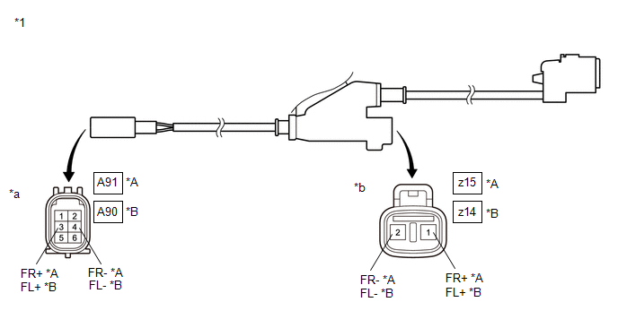
| *A | for RH | *B | for LH |
| *1 | Front Skid Control Sensor Wire | - | - |
| *a | Front view of wire harness connector (to Vehicle Side Connector) | *b | Front view of wire harness connector (to Front Speed Sensor Side Connector) |
Standard Resistance:
for Front Skid Control Sensor Wire RH:| Tester Connection | Condition | Specified Condition |
|---|---|---|
| z15-1 (FR+) - A91-3 (FR+) | Always | Below 1 Ω |
| z15-2 (FR-) - A91-4 (FR-) | Always | |
| z15-1 (FR+) or A91-3 (FR+) - Body ground and other terminals | Always | 10 kΩ or higher |
| z15-2 (FR-) or A91-4 (FR-) - Body ground and other terminals | Always |
| Tester Connection | Condition | Specified Condition |
|---|---|---|
| z14-1 (FL+) - A90-3 (FL+) | Always | Below 1 Ω |
| z14-2 (FL-) - A90-4 (FL-) | Always | |
| z14-1 (FL+) or A90-3 (FL+) - Body ground and other terminals | Always | 10 kΩ or higher |
| z14-2 (FL-) or A90-4 (FL-) - Body ground and other terminals | Always |
(e) Connect the A90, A91, z14 and/or z15 front skid control sensor wire connector(s).
(f) Disconnect the T7, T8, z22 and/or z23 rear No. 1 skid control sensor wire connector(s).
| (g) Measure the resistance according to the value(s) in the table below. Standard Resistance: for Rear No. 1 Skid Control Sensor Wire RH:
|
|
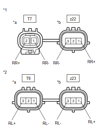
(h) Connect the T7, T8, z22 and/or z23 rear No. 1 skid control sensor wire connector(s).
| NG | | REPAIR OR REPLACE SKID CONTROL SENSOR WIRE |
|
| 6. | PERFORM TEST MODE (SIGNAL CHECK) |
(a) Turn the engine switch off.
(b) Perform the sensor check in the Test Mode procedure.
Click here
| Tester Display |
|---|
| Signal Check |
OK:
All Test Mode (signal check) inspection items are normal.
| NG | | GO TO STEP 8 |
|
| 7. | RECONFIRM DTC |
(a) Clear the DTCs.
Click here
(b) Start the engine.
(c) Drive the vehicle at a speed of 30 km/h (19 mph) or more and check that the same DTC is output.
Click here
| Result | Proceed to |
|---|---|
| DTC is not output | A |
| DTC is output | B |
| A | | CHECK FOR INTERMITTENT PROBLEMS |
| B | | REPLACE BRAKE ACTUATOR ASSEMBLY |
| 8. | CHECK SPEED SENSOR ROTOR |
(a) Turn the engine switch off.
(b) Remove the front speed sensor rotor (front axle hub sub-assembly) or rear speed sensor rotor (rear axle hub and bearing assembly).
for Front: Click here
for Rear: Click here
(c) Check the speed sensor rotor.
OK:
There is no foreign matter, scratches or oil on the rotors.
NOTICE:
Check the speed sensor signal after cleaning or replacement.
Click here
HINT:
- If the front speed sensor rotor needs to be replaced, replace the front axle hub bearing assembly.
- If the rear speed sensor rotor needs to be replaced, replace the rear axle hub and bearing assembly.
| NG | | CLEAN OR REPLACE SPEED SENSOR ROTOR |
|
| 9. | REPLACE SPEED SENSOR |
(a) Turn the engine switch off.
(b) Replace the front speed sensor or the rear speed sensor.
for Front: Click here
for Rear: Click here
NOTICE:
Check the speed sensor signal after replacement.
Click here
|
| 10. | RECONFIRM DTC |
(a) Clear the DTCs.
Click here
(b) Start the engine.
(c) Drive the vehicle at a speed of 30 km/h (19 mph) or more and check that the same DTC is output.
Click here
| Result | Proceed to |
|---|---|
| DTC is output | A |
| DTC is not output | B |
HINT:
Reinstall the sensor, connectors, etc. and restore the vehicle to its prior condition before rechecking DTCs.
| B | | END |
|
| 11. | REPLACE BRAKE ACTUATOR ASSEMBLY |
(a) Replace the skid control ECU (brake actuator assembly).
Click here
|
| 12. | RECONFIRM DTC |
(a) Clear the DTCs.
Click here
(b) Start the engine.
(c) Drive the vehicle at a speed of 30 km/h (19 mph) or more and check that the same DTC is output.
Click here
| Result | Proceed to |
|---|---|
| DTC is not output | A |
| DTC is output | B |
| A | | END |
| B | | REPLACE 4WD ECU ASSEMBLY |
 Cancellation of 4WD Control (C1299)
DESCRIPTION This DTC is stored if the heat generated by the transmission coupling assembly exceeds a certain amount or the estimated oil temperature of the transfer exceeds a certain amount while driv ...
 Control Module Communication Bus Off (U0073)
DESCRIPTION The 4WD ECU assembly stores this DTC when a communication malfunction is detected. DTC No. Detection Item DTC Detection Condition Trouble Area U0073 Control Module Communica ...
Other materials:
Lexus RX (RX 350L, RX450h) 2016-2026 Repair Manual > Shift Lever: Reassembly
REASSEMBLY PROCEDURE 1. INSTALL SHIFT POSITION INDICATOR (a) Install the shift position indicator and console box bracket to the upper console panel sub-assembly with the 2 screws. *1 Console Box Bracket *2 Shift Position Indicator 2. INSTALL ELECTRIC PARKING BRAKE S ...
Lexus RX (RX 350L, RX450h) 2016-2026 Repair Manual > Panoramic View Monitor System: Front Camera Feedback Malfunction (C1681)
DESCRIPTION DTC C1681 is stored if the parking assist ECU judges as a result of its self check that a synchronization problem is occurring in the image signal sent from the front television camera assembly to the parking assist ECU. DTC No. Detection Item DTC Detection Condition Trouble Are ...
Lexus RX (RX 350L, RX450h) 2016-{YEAR} Owners Manual
- For your information
- Pictorial index
- For safety and security
- Instrument cluster
- Operation of each component
- Driving
- Lexus Display Audio system
- Interior features
- Maintenance and care
- When trouble arises
- Vehicle specifications
- For owners
Lexus RX (RX 350L, RX450h) 2016-{YEAR} Repair Manual

0.0201