Lexus RX (RX 350L, RX450h) 2016-2026 Repair Manual: Reassembly
REASSEMBLY
PROCEDURE
1. INSTALL REAR TRANSFER DRIVEN PINION BEARING (OUTER RACE)
| (a) Using SST and a press, install the rear transfer driven pinion bearing (outer race) to the transfer case sub-assembly. SST: 09950-60010 09951-00620 SST: 09950-70010 09951-07150 NOTICE:
|
|
(b) Apply gear oil to the rear transfer driven pinion bearing (outer race).
2. INSTALL TRANSFER OUTPUT SHAFT WASHER
(a) Apply gear oil to the transfer output shaft washer.
(b) Install the transfer output shaft washer to the transfer case sub-assembly.
NOTICE:
If the transfer output shaft washer is damaged or deformed, replace it with a new one.
HINT:
Install the same transfer output shaft washer as the one removed.
3. INSTALL FRONT TRANSFER DRIVEN PINION BEARING
(a) Apply gear oil to the inner surface of the transfer case sub-assembly.
| (b) Using SST, bolt and nut, install the front transfer driven pinion bearing (outer race) to the transfer case sub-assembly. SST: 09950-60010 09951-00610 09951-00620 09951-00650 SST: 09950-60020 09951-00680 NOTICE:
|
|
(c) Apply gear oil to the front transfer driven pinion bearing (outer race).
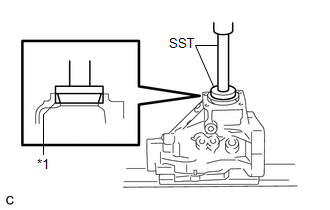
| (d) Using SST and a press, install the front transfer driven pinion bearing (inner race) to the driven pinion. SST: 09506-30012 NOTICE:
|
|
(e) Apply gear oil to the front transfer driven pinion bearing (inner race).
4. INSTALL DRIVEN PINION
| (a) Install the driven pinion to the transfer case sub-assembly. |
|
| (b) Apply gear oil to the rear transfer driven pinion bearing (inner race). |
|
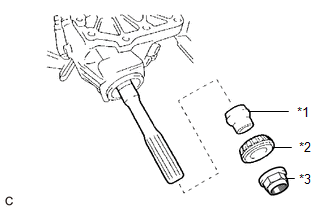
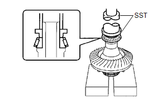
(c) Install a new transfer pinion bearing spacer and the rear transfer driven pinion bearing (inner race) to the driven pinion.
NOTICE:
- If the rear transfer driven pinion bearing (inner race) is damaged or deformed, replace it with a new one.
- When replacing the rear transfer driven pinion bearing (inner race), replace both outer and inner races as one set.
HINT:
Install the transfer pinion bearing spacer with the larger inner diameter facing forward as shown in the illustration.
(d) Apply hypoid gear oil LSD to the threads of a new gear nut and its seating surface.
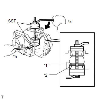
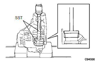
| (e) Using SST, install the gear nut. SST: 09326-20011 SST: 09556-16030 Torque: Specified tightening torque 270 to 420 N*m (2753 to 4283 kgf*cm, 199 to 310 ft.*lbf) NOTICE:
HINT:
|
|
5. ADJUST DRIVEN PINION PRELOAD
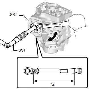
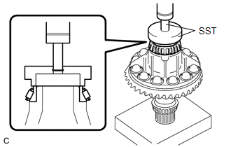
| (a) Using SST and a torque wrench, measure the driven pinion preload. SST: 09326-20011 Specified Preload (at Starting)
NOTICE: Turn the driven pinion counterclockwise and clockwise several times. HINT:
|
|
(b) If the preload is more than the specification, replace the transfer pinion bearing spacer with a new one.
(c) If the preload is not sufficient, adjust the driven pinion by tightening the gear nut 5° to 10° and measuring the preload until the preload is within the specification.
(d) Even if the tightening torque of the gear nut exceeds the specified torque, if the preload is insufficient, loosen the gear nut once and apply rust preventive oil or hypoid gear oil LSD to the gear nut and to the screw or rear transfer driven pinion bearing (inner race) surface of the driven pinion. Then perform the procedure again. If the tightening torque is less than the specified torque, replace the transfer pinion bearing spacer with a new one and adjust it.
NOTICE:
Do not loosen the gear nut to reduce the preload.
6. INSTALL RING GEAR
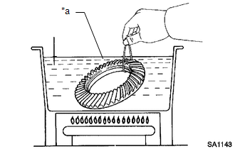
| (a) Heat the ring gear in boiling water. |
|
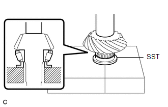
(b) Secure the transfer ring gear mounting case in a vise using aluminum plates.
NOTICE:
- Be careful not to damage the transfer ring gear mounting case in the vise.
- Remove any oil and water from the ring gear contact surface of the transfer ring gear mounting case.
- Clean the bolt holes in the transfer ring gear mounting case.
(c) Carefully remove the ring gear from the boiling water.
CAUTION:
Make sure to wear protective gloves as the ring gear is extremely hot.
| (d) After the moisture on the ring gear has completely evaporated, quickly align the matchmarks and set the ring gear to the transfer ring gear mounting case. NOTICE: There is no foreign matter on the contact surfaces of the transfer ring gear mounting case and ring gear. |
|
(e) Apply adhesive to the bolt holes and contact surface of the 12 bolts.
Adhesive:
Toyota Genuine Adhesive 1324, Three Bond 1324 or equivalent
NOTICE:
- Apply adhesive after the ring gear has cooled down sufficiently.
- Make sure to install the bolts immediately after applying adhesive to keep foreign matter away from them.
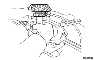
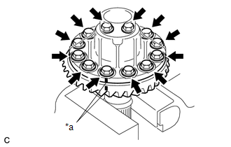
(f) Install the ring gear with the 12 bolts.
Torque:
98.6 N·m {1005 kgf·cm, 73 ft·lbf}
NOTICE:
- Tighten the bolts evenly in a diagonal pattern using several steps.
- Tighten the bolts after the ring gear has cooled down sufficiently.
7. INSTALL RING GEAR MOUNTING CASE BEARING
(a) for LH side:
| (1) Using SST and a press, install the ring gear mounting case bearing (inner race) to the transfer ring gear mounting case. SST: 09223-00010 SST: 09726-40010 NOTICE:
|
|
(2) Install the ring gear mounting case plate washer to the transfer case sub-assembly.
NOTICE:
If the ring gear mounting case plate washer is damaged or deformed, replace it with a new one.
HINT:
Use a new ring gear mounting case plate washer with the same thickness as the one removed when installing the ring gear mounting case bearing (outer race).
| (3) Using SST and a press, install the ring gear mounting case bearing (outer race) to the transfer case sub-assembly. SST: 09950-60010 09951-00680 SST: 09950-70010 09951-07200 NOTICE:
|
|
(4) Apply gear oil to the ring gear mounting case bearing.
(b) for RH side:
| (1) Using SST and a press, install the ring gear mounting case bearing (inner race) to the transfer ring gear mounting case. SST: 09387-00010 SST: 09950-70010 09951-07100 NOTICE:
|
|
(2) Install the ring gear mounting case bearing (outer race) to the transfer ring gear mounting case.
NOTICE:
- If the ring gear mounting case bearing (outer race) is damaged or deformed, replace it with a new one.
- When replacing the ring gear mounting case bearing (outer race), replace both outer and inner races as one set.
(3) Apply gear oil to the ring gear mounting case bearing.
8. INSTALL TRANSFER RING GEAR MOUNTING CASE
| (a) Install the transfer ring gear mounting case to the transfer case sub-assembly. |
|
.png)
9. INSTALL NO. 1 TRANSFER OUTPUT SHAFT SPACER
(a) Apply gear oil to the No. 1 transfer output shaft spacer.
| (b) Align the cutout on the No. 1 transfer output shaft spacer with the transfer case hole to install it as shown in the illustration. |
|
10. INSTALL NO. 2 TRANSFER RING GEAR MOUNTING CASE WASHER
(a) Apply gear oil to the No. 2 transfer ring gear mounting case washer.
| (b) Using a brass bar and a hammer, install the No. 2 transfer ring gear mounting case washer to the transfer case sub-assembly. HINT: Use a No. 2 transfer ring gear mounting case washer with the same thickness as the one removed. |
|
11. INSTALL BEARING CAP
| (a) Install the bearing cap to the transfer case sub-assembly with the 2 bolts. Torque: 63.2 N·m {644 kgf·cm, 47 ft·lbf} |
|
.png)
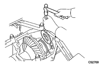
12. INSPECT RING GEAR BACKLASH
| (a) Set a dial indicator perpendicular to a ring gear tooth tip. |
|
.png)
(b) Secure the driven pinion in place and move the ring gear back and forth to measure the backlash.
Backlash:
0.14 to 0.25 mm (0.00551 to 0.00984 in.)
NOTICE:
Check at least 3 positions on the circumference of the ring gear.
| (c) If the backlash is outside the specified range, select a ring gear mounting case plate washer from the table below and install it to meet the specified range. HINT: If the backlash is more than specified, select a thinner ring gear mounting case plate washer. If the backlash is less than specified, select a thicker ring gear mounting case plate washer. Ring Gear Mounting Case Plate Washer Thickness:
|
|
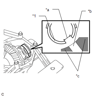
13. INSPECT TOOTH CONTACT BETWEEN RING GEAR AND DRIVEN PINION
| (a) Apply a light coat of Prussian blue evenly to both sides of all teeth. |
|
.png)
(b) Rotate the ring gear 10 times or more.
(c) Rotate the ring gear to inspect the tooth contact pattern.
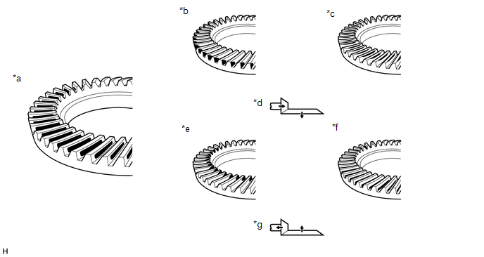
| *a | Proper Contact | *b | Heel Contact |
| *c | Face Contact | *d | Select an adjusting washer that will shift the driven pinion closer to the ring gear (*b, *c) |
| *e | Toe Contact | *f | Flank Contact |
| *g | Select an adjusting washer that will shift the driven pinion away from the ring gear (*e, *f) | - | - |
NOTICE:
Check at least 4 positions on the circumference of the ring gear.
HINT:
Prussian blue shown in the illustration indicates the tooth contact pattern.
| (d) If the tooth contact pattern is not correct, select a new transfer output shaft washer that is thicker or thinner as necessary and recheck. NOTICE: When the transfer output shaft washer thickness is changed, readjust the backlash. Click here Transfer Output Shaft Washer Thickness:
|
|
14. INSPECT AND ADJUST TOTAL PRELOAD
(a) Using SST and a torque wrench, measure the total preload.
.png)
| *a | Torque Wrench Fulcrum Length |
SST: 09326-20011
Specified Total Preload (at Starting)| Item | Preload |
|---|---|
| New bearing | 0.5 to 0.7 N*m (5 to 7 kgf*cm, 4 to 6 in.*lbf) + Driven pinion preload |
| Reused bearing | 0.4 to 0.5 N*m (4.1 to 5.1 kgf*cm, 3.5 to 4.4 in.*lbf) + Driven pinion preload |
NOTICE:
Turn the driven pinion counterclockwise and clockwise several times.
HINT:
-
Calculate the torque wrench reading when changing the fulcrum length of the torque wrench.
Click here
.gif)
-
When using SST (fulcrum length of 50 mm (1.97 in.)) + torque wrench (fulcrum length of 130 mm (5.12 in.)): Total Preload (at Starting)
Item
Preload
New bearing
0.4 to 0.5 N*m (4.1 to 5.1 kgf*cm, 3.5 to 4.4 in.*lbf) + Driven pinion preload
Reused bearing
0.25 to 0.38 N*m (3 to 4 kgf*cm, 2 to 3 in.*lbf) + Driven pinion preload
If the preload is outside the specified range, replace the No. 2 transfer ring gear mounting case washer with one that is thicker or thinner as necessary and recheck.
| *1 | No. 2 Transfer Ring Gear Mounting Case Washer |
No. 2 Transfer Ring Gear Mounting Case Washer Thickness:
| Part Number | Thickness (mm (in.)) | Mark | Part Number | Thickness (mm (in.)) | Mark |
|---|---|---|---|---|---|
| 36266-48220 | 2.47 (0.0972) | G7 | 36266-48720 | 3.47 (0.13661) | M7 |
| 36266-48230 | 2.49 (0.0980) | G8 | 36266-48730 | 3.49 (0.13740) | M8 |
| 36266-48240 | 2.51 (0.0988) | G9 | 36266-48740 | 3.51 (0.138) | M9 |
| 36266-48250 | 2.53 (0.0996) | H0 | 36266-48750 | 3.53 (0.139) | N0 |
| 36266-48260 | 2.55 (0.100) | H1 | 36266-48760 | 3.55 (0.13976) | N1 |
| 36266-48270 | 2.57 (0.101) | H2 | 36266-48770 | 3.57 (0.14055) | N2 |
| 36266-48280 | 2.59 (0.102) | H3 | 36266-48780 | 3.59 (0.14134) | N3 |
| 36266-48290 | 2.61 (0.103) | H4 | 36266-48790 | 3.61 (0.142) | N4 |
| 36266-48300 | 2.63 (0.10354) | H5 | 36266-48800 | 3.63 (0.143) | N5 |
| 36266-48310 | 2.65 (0.10433) | H6 | 36266-48810 | 3.65 (0.14370) | N6 |
| 36266-48320 | 2.67 (0.105) | H7 | 36266-48820 | 3.67 (0.14449) | N7 |
| 36266-48330 | 2.69 (0.106) | H8 | 36266-48830 | 3.69 (0.145) | N8 |
| 36266-48340 | 2.71 (0.10669) | H9 | 36266-48840 | 3.71 (0.146) | N9 |
| 36266-48350 | 2.73 (0.10748) | J0 | 36266-48850 | 3.73 (0.147) | P0 |
| 36266-48360 | 2.75 (0.108) | J1 | 36266-48860 | 3.75 (0.14764) | P1 |
| 36266-48370 | 2.77 (0.109) | J2 | 36266-48870 | 3.77 (0.14842) | P2 |
| 36266-48380 | 2.79 (0.110) | J3 | 36266-48880 | 3.79 (0.149) | P3 |
| 36266-48390 | 2.81 (0.11063) | J4 | 36266-48890 | 3.81 (0.150) | P4 |
| 36266-48400 | 2.83 (0.11142) | J5 | 36266-48A00 | 3.83 (0.151) | P5 |
| 36266-48410 | 2.85 (0.112) | J6 | 36266-48A10 | 3.85 (0.15157) | P6 |
| 36266-48420 | 2.87 (0.113) | J7 | 36266-48A20 | 3.87 (0.15236) | P7 |
| 36266-48430 | 2.89 (0.114) | J8 | 36266-48A30 | 3.89 (0.153) | P8 |
| 36266-48440 | 2.91 (0.11457) | J9 | 36266-48A40 | 3.91 (0.154) | P9 |
| 36266-48450 | 2.93 (0.11535) | K0 | 36266-48A50 | 3.93 (0.155) | Q0 |
| 36266-48460 | 2.95 (0.116) | K1 | 36266-48A60 | 3.95 (0.15551) | Q1 |
| 36266-48470 | 2.97 (0.117) | K2 | 36266-48A70 | 3.97 (0.15630) | Q2 |
| 36266-48480 | 2.99 (0.118) | K3 | 36266-48A80 | 3.99 (0.157) | Q3 |
| 36266-48490 | 3.01 (0.11850) | K4 | 36266-48A90 | 4.01 (0.158) | Q4 |
| 36266-48500 | 3.03 (0.11929) | K5 | 36266-48B00 | 4.03 (0.15866) | Q5 |
| 36266-48510 | 3.05 (0.120) | K6 | 36266-48B10 | 4.05 (0.15945) | Q6 |
| 36266-48520 | 3.07 (0.121) | K7 | 36266-48B20 | 4.07 (0.160) | Q7 |
| 36266-48530 | 3.09 (0.12165) | K8 | 36266-48B30 | 4.09 (0.161) | Q8 |
| 36266-48540 | 3.11 (0.12244) | K9 | 36266-48B40 | 4.11 (0.162) | Q9 |
| 36266-48550 | 3.13 (0.123) | L0 | 36266-48B50 | 4.13 (0.16260) | R0 |
| 36266-48560 | 3.15 (0.124) | L1 | 36266-48B60 | 4.15 (0.16339) | R1 |
| 36266-48570 | 3.17 (0.125) | L2 | 36266-48B70 | 4.17 (0.164) | R2 |
| 36266-48580 | 3.19 (0.12559) | L3 | 36266-48B80 | 4.19 (0.165) | R3 |
| 36266-48590 | 3.21 (0.12638) | L4 | 36266-48B90 | 4.21 (0.166) | R4 |
| 36266-48600 | 3.23 (0.127) | L5 | 36266-48C00 | 4.23 (0.16654) | R5 |
| 36266-48610 | 3.25 (0.128) | L6 | 36266-48C10 | 4.25 (0.16732) | R6 |
| 36266-48620 | 3.27 (0.129) | L7 | 36266-48C20 | 4.27 (0.168) | R7 |
| 36266-48630 | 3.29 (0.12953) | L8 | 36266-48C30 | 4.29 (0.169) | R8 |
| 36266-48640 | 3.31 (0.13031) | L9 | 36266-48C40 | 4.31 (0.16968) | R9 |
| 36266-48650 | 3.33 (0.131) | M0 | 36266-48C50 | 4.33 (0.17047) | S0 |
| 36266-48660 | 3.35 (0.132) | M1 | 36266-48C60 | 4.35 (0.171) | S1 |
| 36266-48670 | 3.37 (0.13268) | M2 | 36266-48C70 | 4.37 (0.172) | S2 |
| 36266-48680 | 3.39 (0.13346) | M3 | 36266-48C80 | 4.39 (0.173) | S3 |
| 36266-48690 | 3.41 (0.134) | M4 | 36266-48C90 | 4.41 (0.17362) | S4 |
| 36266-48700 | 3.43 (0.135) | M5 | 36266-48D00 | 4.43 (0.17441) | S5 |
| 36266-48710 | 3.45 (0.136) | M6 | 36266-48D10 | 4.45 (0.175) | S6 |
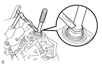
| (b) Using a chisel and a hammer, stake the gear nut. |
|
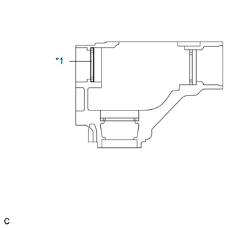
15. INSTALL TRANSFER CASE OIL SEAL RH
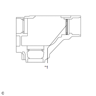
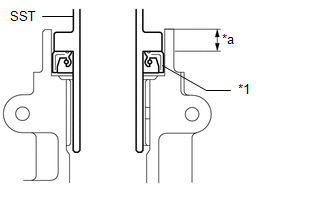
(a) Using SST and a hammer, install a new transfer case oil seal RH to the transfer case sub-assembly until it reaches the position shown in the illustration.
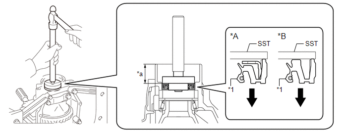
| *A | Type A | *B | Type B |
| *1 | Transfer Case Oil Seal RH | - | - |
| *a | Depth | - | - |
.png) | Install in this Direction | - | - |
SST: 09950-60010
09951-00340
09951-00580
09952-06010
SST: 09950-70010
09951-07150
Standard Depth:
33.5 to 34.5 mm (1.32 to 1.36 in.)
NOTICE:
- Be sure to install the transfer case oil seal RH in the correct orientation.
- Make sure that the transfer case oil seal RH is not tilted.
- Do not tap in the transfer case oil seal RH in too far.
(b) Coat the lip of the transfer case oil seal RH with MP grease.
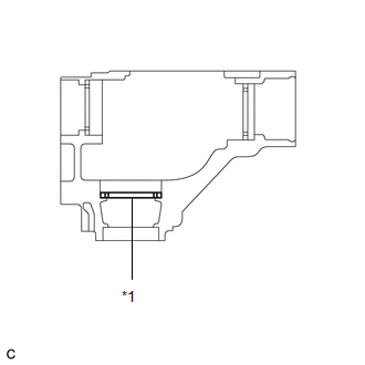
16. INSTALL TRANSFER CASE OIL SEAL
| (a) Using SST and a hammer, install a new transfer case oil seal to the transfer case sub-assembly until it reaches the position shown in the illustration. SST: 09608-10010 SST: 09950-70010 09951-07150 Standard Depth: 9.5 to 10.5 mm (0.374 to 0.413 in.) NOTICE:
|
|
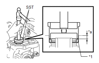
(b) Coat the lip of the transfer case oil seal with MP grease.
17. INSTALL TRANSFER EXTENSION HOUSING TYPE T OIL SEAL
| (a) Using SST and a hammer, install a new transfer extension housing type T oil seal to the transfer extension housing sub-assembly until it reaches the position shown in the illustration. SST: 09325-20010 Standard Depth: 9.8 to 10.6 mm (0.386 to 0.417 in.) NOTICE:
|
|
(b) Coat the lip of the transfer extension housing type T oil seal with MP grease.
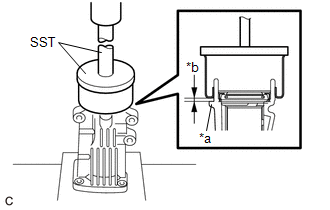
18. INSTALL TRANSFER EXTENSION HOUSING DUST DEFLECTOR
| (a) Using SST and a press, install a new transfer extension housing dust deflector to the transfer extension housing sub-assembly so that the clearance between the rib of the transfer extension housing sub-assembly and the transfer extension housing dust deflector is approximately 1 to 2 mm. SST: 09950-60020 09951-01030 SST: 09950-70010 09951-07150 |
|
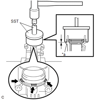
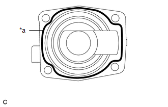
| (b) Using SST and a hammer, tap in the transfer extension housing dust deflector until it contacts the rib of the transfer extension housing sub-assembly. SST: 09950-60020 09951-01030 SST: 09950-70010 09951-07150 NOTICE: Make sure that the transfer extension housing dust deflector evenly contacts the 3 ribs of the transfer extension housing sub-assembly. |
|
19. INSTALL TRANSFER EXTENSION HOUSING SUB-ASSEMBLY
(a) Remove any FIPG and be careful not to drop oil on the contact surfaces of the transfer extension housing sub-assembly and transfer case sub-assembly.
(b) Degrease the surfaces with a non-residue solvent.
| (c) Apply FIPG to the transfer extension housing sub-assembly. FIPG: Toyota Genuine Seal Packing 1281, Three Bond 1281 or equivalent NOTICE:
|
|
| (d) Install the transfer extension housing sub-assembly to the transfer case sub-assembly with the 4 bolts. Torque: 25.5 N·m {260 kgf·cm, 19 ft·lbf} |
|
20. REMOVE TRANSFER ASSEMBLY
(a) Remove the transfer assembly from the overhaul attachment.
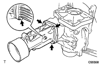
21. INSTALL TRANSFER CASE STRAIGHT PIN
(a) Using a plastic hammer, install the 4 transfer case straight pins to the transfer case sub-assembly at the positions shown in the illustration.
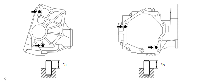
| *a | 10.8 to 11.8 mm (0.425 to 0.465 in.) | *b | 5.7 to 6.7 mm (0.224 to 0.264 in.) |
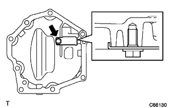
22. INSTALL BREATHER OIL DEFLECTOR
| (a) Install the breather oil deflector to the transfer case cover sub-assembly with the bolt. Torque: 6.5 N·m {66 kgf·cm, 58 in·lbf} NOTICE: Make sure that the breather oil deflector is installed in the correct direction. |
|
23. INSTALL TRANSFER CASE COVER SUB-ASSEMBLY
(a) Remove any FIPG and be careful not to drop oil on the contact surfaces of the transfer case cover sub-assembly and transfer case sub-assembly.
(b) Degrease the surfaces with a non-residue solvent.
| (c) Apply FIPG to the transfer case cover sub-assembly. FIPG: Toyota Genuine Seal Packing 1281, Three Bond 1281 or equivalent NOTICE:
|
|
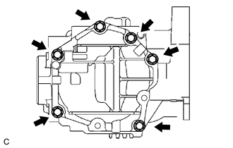
| (d) Install the transfer case cover sub-assembly to the transfer case sub-assembly with the 6 bolts. Torque: 19.6 N·m {200 kgf·cm, 14 ft·lbf} |
|
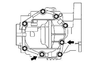
| (e) Install 2 new bolts. Torque: 19.6 N·m {200 kgf·cm, 14 ft·lbf} NOTICE: Wait for at least 1 hour after installing the transfer case cover sub-assembly before adding transfer oil. |
|
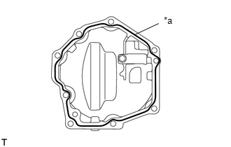
24. INSTALL TRANSFER CASE BREATHER PLUG
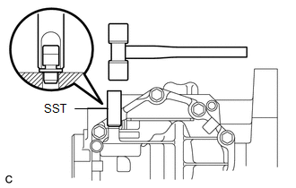
| (a) Using SST and a hammer, install a new transfer case breather plug to the transfer case cover sub-assembly. SST: 09612-10093 09612-10061 |
|
25. INSTALL TRANSFER DRAIN PLUG
(a) Install a new gasket to the transfer drain plug.
| (b) Install the transfer drain plug to the transfer case sub-assembly. Torque: 49 N·m {500 kgf·cm, 36 ft·lbf} |
|
.png)
26. INSTALL FILLER PLUG (NO. 1 TRANSFER CASE PLUG)
| (a) Install a new gasket to the filler plug (No. 1 transfer case plug). |
|
.png)
(b) Install the filler plug (No. 1 transfer case plug) to the transfer case sub-assembly.
Torque:
49 N·m {500 kgf·cm, 36 ft·lbf}
27. INSTALL NO. 2 TRANSFER CASE PLUG
| (a) Install a new gasket to the No. 2 transfer case plug. |
|
.png)
(b) Install the No. 2 transfer case plug to the transfer case sub-assembly.
Torque:
49 N·m {500 kgf·cm, 36 ft·lbf}
28. INSTALL TRANSFER AND TRANSAXLE SETTING STUD BOLT
(a) Install 4 new transfer and transaxle setting stud bolts to the transfer case sub-assembly at the positions shown in the illustration.
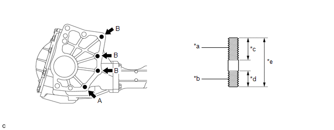
| *a | Automatic Transaxle Assembly Side | *b | Transfer Case Sub-assembly Side |
| *c | 30 mm (1.18 in.) | *d | 22 mm (0.866 in.) |
| *e | 64 mm (2.52 in.) | - | - |
Torque:
Transfer and Transaxle Setting Stud Bolt (A) :
39.2 N·m {400 kgf·cm, 29 ft·lbf}
Transfer and Transaxle Setting Stud Bolt (B) :
25 N·m {255 kgf·cm, 18 ft·lbf}
NOTICE:
Install the sealed side of the transfer and transaxle setting stud bolt to the transfer case sub-assembly.
 Disassembly
DISASSEMBLY CAUTION / NOTICE / HINT NOTICE: Before installation of each part, thoroughly clean and dry it. Then apply grease or oil as necessary. Do not use alkaline chemicals to clean aluminum parts, ...

Other materials:
Lexus RX (RX 350L, RX450h) 2016-2026 Repair Manual > Smart Access System With Push-button Start (for Start Function): Dtc Check / Clear
DTC CHECK / CLEAR NOTICE: When using the Techstream with the engine switch off, connect the Techstream to the DLC3 and turn a courtesy light switch on and off at intervals of 1.5 seconds or less until communication between the Techstream and the vehicle begins. Then select the vehicle type under man ...
Lexus RX (RX 350L, RX450h) 2016-2026 Repair Manual > Rear Power Seat Control System(for Second Row): Park / Neutral Position Switch Circuit
DESCRIPTION The fold seat control ECU receives switch operation signals, the back door courtesy light switch assembly signal*1, rear door courtesy light switch assembly signal*2 and driving condition signal and operates the rear power seat according these signals.
*1: When using fold seat switch ...
Lexus RX (RX 350L, RX450h) 2016-{YEAR} Owners Manual
- For your information
- Pictorial index
- For safety and security
- Instrument cluster
- Operation of each component
- Driving
- Lexus Display Audio system
- Interior features
- Maintenance and care
- When trouble arises
- Vehicle specifications
- For owners
Lexus RX (RX 350L, RX450h) 2016-{YEAR} Repair Manual

0.016