Lexus RX (RX 350L, RX450h) 2016-2026 Repair Manual: Disassembly
DISASSEMBLY
CAUTION / NOTICE / HINT
NOTICE:
Before installation of each part, thoroughly clean and dry it. Then apply grease or oil as necessary. Do not use alkaline chemicals to clean aluminum parts, rubber parts or precoated bolts. Also, do not use non-residue solvent or other cleaning oils to clean O-rings, oil seals or rubber parts.
PROCEDURE
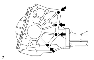
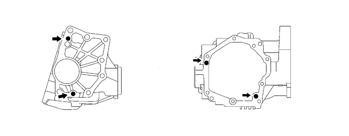
1. REMOVE TRANSFER AND TRANSAXLE SETTING STUD BOLT
| (a) Remove the 4 transfer and transaxle setting stud bolts from the transfer case sub-assembly. |
|
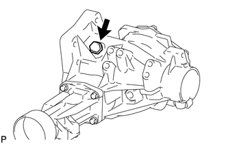
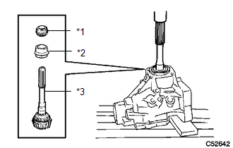
2. REMOVE NO. 2 TRANSFER CASE PLUG
| (a) Remove the No. 2 transfer case plug from the transfer case sub-assembly. |
|
(b) Remove the gasket from the No. 2 transfer case plug.
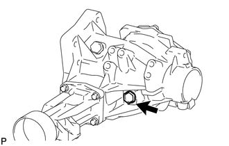
3. REMOVE FILLER PLUG (NO. 1 TRANSFER CASE PLUG)
| (a) Remove the filler plug (No. 1 transfer case plug) from the transfer case sub-assembly. |
|
(b) Remove the gasket from the filler plug (No. 1 transfer case plug).
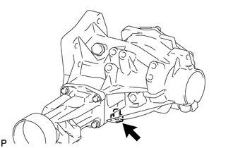
4. REMOVE TRANSFER DRAIN PLUG
| (a) Remove the transfer drain plug from the transfer case sub-assembly. |
|
(b) Remove the gasket from the transfer drain plug.
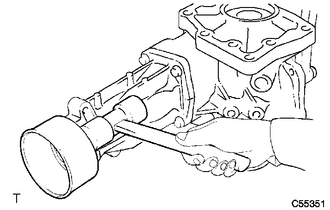
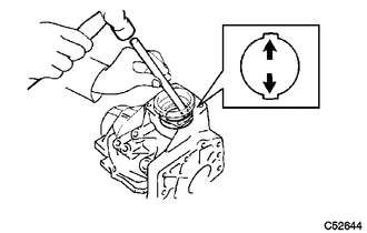
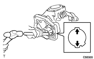
5. REMOVE TRANSFER CASE BREATHER PLUG
| (a) Using a chisel and hammer, lift the transfer case breather plug slightly. |
|
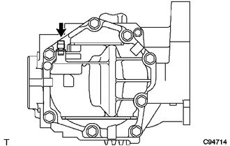
(b) Using a screwdriver, remove the transfer case breather plug from the transfer case cover sub-assembly.
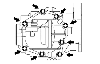
6. REMOVE TRANSFER CASE COVER SUB-ASSEMBLY
| (a) Remove the 8 bolts from the transfer case cover sub-assembly. |
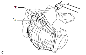
|
| (b) Using a brass bar and a hammer, remove the transfer case cover sub-assembly from the transfer case sub-assembly. NOTICE: Place the brass bar on the rib protruding from the transfer case cover sub-assembly. |
|
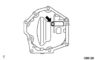
7. REMOVE BREATHER OIL DEFLECTOR
| (a) Remove the bolt and breather oil deflector from the transfer case cover sub-assembly. |
|
8. REMOVE TRANSFER CASE STRAIGHT PIN
(a) Remove the 4 transfer case straight pins from the transfer case sub-assembly.
9. SECURE TRANSFER ASSEMBLY
(a) Attach the transfer assembly to the overhaul attachment.
10. REMOVE TRANSFER EXTENSION HOUSING DUST DEFLECTOR
HINT:
Only perform this procedure when replacement of the transfer extension housing dust deflector or transfer extension housing sub-assembly is necessary.
| (a) Using a plastic hammer, remove the transfer extension housing dust deflector from the transfer extension housing sub-assembly. |
|
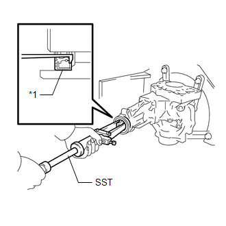
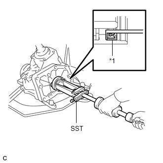
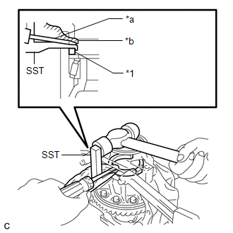
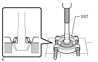
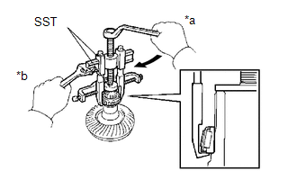
11. REMOVE TRANSFER EXTENSION HOUSING TYPE T OIL SEAL
| (a) Using SST, remove the transfer extension housing type T oil seal from the transfer extension housing sub-assembly. SST: 09308-00010 NOTICE: Be careful not to damage the transfer extension housing type T oil seal contact surface or the inside surface of the transfer extension housing type T oil seal. |
|
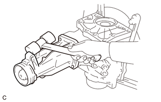
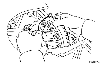
12. REMOVE TRANSFER EXTENSION HOUSING SUB-ASSEMBLY
| (a) Remove the 4 bolts. |
|
| (b) Using a plastic hammer, remove the transfer extension housing sub-assembly from the transfer case sub-assembly. |
|
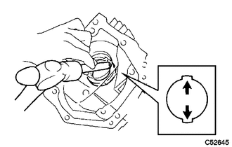
13. INSPECT PRELOAD
Click here .gif)
14. INSPECT RING GEAR BACKLASH
Click here
15. INSPECT TOOTH CONTACT BETWEEN RING GEAR AND DRIVEN PINION
Click here
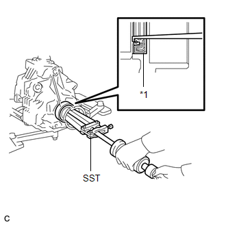
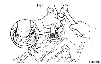
16. REMOVE TRANSFER CASE OIL SEAL
| (a) Using SST, remove the transfer case oil seal from the transfer case sub-assembly. SST: 09308-00010 NOTICE:
|
|
17. REMOVE TRANSFER CASE OIL SEAL RH
| (a) Using SST, remove the transfer case oil seal RH from the transfer case sub-assembly. SST: 09308-00010 NOTICE: Do not damage the transfer case oil seal RH contact surface to the transfer case sub-assembly. |
|
18. REMOVE BEARING CAP
| (a) Remove the 2 bolts and bearing cap from the transfer case sub-assembly. |
|
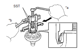
19. REMOVE NO. 1 TRANSFER OUTPUT SHAFT SPACER
| (a) Using SST, a screwdriver and a hammer, remove the No. 1 transfer output shaft spacer from the transfer case sub-assembly. SST: 09504-22012 NOTICE: Do not damage the transfer case sub-assembly. |
|
20. REMOVE NO. 2 TRANSFER RING GEAR MOUNTING CASE WASHER
(a) Remove the No. 2 transfer ring gear mounting case washer from the transfer case sub-assembly.
21. REMOVE TRANSFER RING GEAR MOUNTING CASE
| (a) Remove the transfer ring gear mounting case from the transfer case sub-assembly. |
|
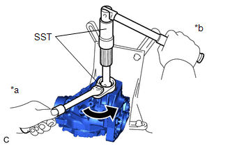
22. REMOVE DRIVEN PINION
| (a) Using SST and a hammer, unstake the gear nut. SST: 09930-00010 HINT:
|
|
| (b) Using SST, remove the gear nut. SST: 09326-20011 SST: 09556-16030 |
|
| (c) Using a press, press out the driven pinion, rear transfer driven pinion bearing (inner race) and transfer pinion bearing spacer. NOTICE:
|
|
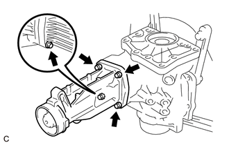
23. REMOVE FRONT TRANSFER DRIVEN PINION BEARING
| (a) Using SST and a press, remove the front transfer driven pinion bearing (inner race) from the driven pinion. SST: 09950-00020 NOTICE:
|
|
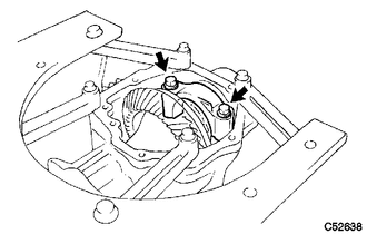
| (b) Using a brass bar and a hammer, tap the 2 positions shown in the illustration on the front transfer driven pinion bearing (outer race) to remove it from the transfer case sub-assembly. NOTICE: Fit the brass bar to the 2 cutouts of the transfer case sub-assembly. |
|
24. REMOVE TRANSFER OUTPUT SHAFT WASHER
(a) Remove the transfer output shaft washer from the transfer case sub-assembly.
NOTICE:
If the transfer output shaft washer is damaged or deformed, replace it with a new one.
25. REMOVE RING GEAR MOUNTING CASE BEARING
(a) for RH side:
(1) Remove the ring gear mounting case bearing (outer race) from the transfer ring gear mounting case.
| (2) Using SST, remove the ring gear mounting case bearing (inner race) from the transfer ring gear mounting case. SST: 09950-40011 09951-04010 09952-04010 09953-04020 09954-04010 09955-04061 09957-04010 09958-04011 SST: 09950-60010 09951-00440 NOTICE:
|
|
(b) for LH side:
| (1) Using SST, remove the ring gear mounting case bearing (inner race) from the transfer ring gear mounting case. SST: 09950-40011 09951-04010 09952-04010 09953-04020 09954-04010 09955-04061 09957-04010 09958-04011 SST: 09950-60010 09951-00400 NOTICE:
|
|
| (2) Using a brass bar and a hammer, tap the 2 positions shown in the illustration on the ring gear mounting case bearing (outer race) to remove it from the transfer case sub-assembly. NOTICE: Fit the brass bar to the 2 cutouts of the transfer case sub-assembly. |
|
(3) Remove the ring gear mounting case plate washer from the transfer case sub-assembly.
NOTICE:
If the ring gear mounting case plate washer is damaged or deformed, replace it with a new one.
26. INSPECT RUNOUT OF RING GEAR
Click here
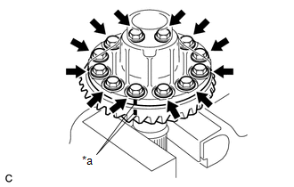
27. REMOVE RING GEAR
(a) Secure the transfer ring gear mounting case in a vise using aluminum plates.
NOTICE:
Be careful not to damage the transfer ring gear mounting case in the vise.
| (b) Put matchmarks on the transfer ring gear mounting case and ring gear. |
|
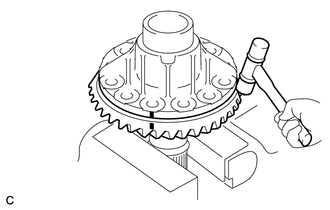
(c) Remove the 12 bolts.
| (d) Using a plastic hammer, remove the ring gear from the transfer ring gear mounting case. NOTICE: Do not damage the ring gear teeth. |
|
28. INSPECT TRANSFER RING GEAR MOUNTING CASE
Click here
29. REMOVE REAR TRANSFER DRIVEN PINION BEARING (OUTER RACE)
| (a) Using a brass bar and a hammer, tap the 2 positions shown in the illustration on the rear transfer driven pinion bearing (outer race) to remove it from the transfer case sub-assembly. NOTICE: Fit the brass bar to the 2 cutouts of the transfer case sub-assembly. |
|
 Installation
INSTALLATION PROCEDURE 1. INSTALL TRANSFER ASSEMBLY (a) Install 4 new transfer and transaxle setting stud bolts to the automatic transaxle assembly positions shown in the illustration. *a 69 mm ...
 Reassembly
REASSEMBLY PROCEDURE 1. INSTALL REAR TRANSFER DRIVEN PINION BEARING (OUTER RACE) (a) Using SST and a press, install the rear transfer driven pinion bearing (outer race) to the transfer case sub-ass ...
Other materials:
Lexus RX (RX 350L, RX450h) 2016-2026 Repair Manual > Wiper And Washer System: Wiper Switch Signal Mismatch between LIN and Line (B1372)
DESCRIPTION Under normal operation, the front wiper motor and link assembly (wiper ECU) receives operation signals from the windshield wiper switch assembly via LIN communication. The windshield front wiper motor and link assembly (wiper ECU) and windshield wiper switch assembly are also connected v ...
Lexus RX (RX 350L, RX450h) 2016-2026 Repair Manual > Automatic Transaxle System: Pressure Control Solenoid "H" Actuator Stuck Off (P28167F)
DESCRIPTION Based on signals from the transmission revolution sensors (NT, NC3 and NC), the actual gear is detected. The ECM compares the actual gear with the shift schedule in the ECM memory to detect mechanical malfunctions of the shift solenoid valves, transmission valve body assembly and automat ...
Lexus RX (RX 350L, RX450h) 2016-{YEAR} Owners Manual
- For your information
- Pictorial index
- For safety and security
- Instrument cluster
- Operation of each component
- Driving
- Lexus Display Audio system
- Interior features
- Maintenance and care
- When trouble arises
- Vehicle specifications
- For owners
Lexus RX (RX 350L, RX450h) 2016-{YEAR} Repair Manual

0.0139