Lexus RX (RX 350L, RX450h) 2016-2026 Repair Manual: Transmission Range Sensor "A" Circuit Open (P070513,P070562)
DESCRIPTION
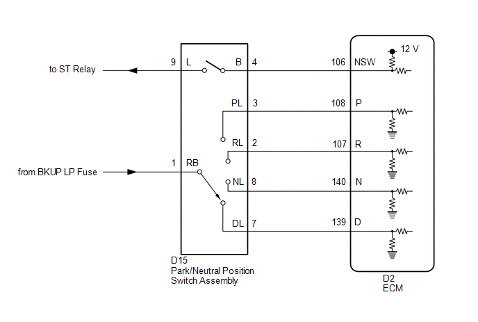
The park/neutral position switch assembly detects the shift lever position and sends signals to the ECM.
| DTC No. | Detection Item | DTC Detection Condition | Trouble Area | MIL | Memory | Note |
|---|---|---|---|---|---|---|
| P070513 | Transmission Range Sensor "A" Circuit Open | 1. Diagnosis Condition 2. Malfunction Status 3. Malfunction Time 4. Other
|
| Comes on | DTC stored | SAE Code: P0705 |
| P070562 | Transmission Range Sensor "A" Signal Compare Failure | 1. Diagnosis Condition 2. Malfunction Status 3. Malfunction Time 4. Other
|
| Comes on | DTC stored | SAE Code: P0705 |
MONITOR DESCRIPTION
These DTCs indicate a problem with the park/neutral position switch assembly or the wire harness in the park/neutral position switch assembly circuit.
The park/neutral position switch assembly detects the shift lever position and sends signals to the ECM.
For safety, the park/neutral position switch assembly detects the shift lever position so that the engine can be started only when the shift lever is in P or N.
The park/neutral position switch assembly sends a signal to the ECM according to the shift lever position (P, N, R, D or M).
The ECM determines that there is a problem with the switch or related parts if it receives more than 1 position signal simultaneously and will then illuminate the MIL and store a DTC.
MONITOR STRATEGY
| Related DTCs | P0705: Park/neutral position switch assembly/Verify switch input |
| Required sensors/Components | Park/neutral position switch |
| Frequency of operation | Continuous |
| Duration | P070513: 60 sec. P070562: 2 sec. |
| MIL operation | 2 driving cycles |
| Sequence of operation | None |
TYPICAL ENABLING CONDITIONS
| The monitor will run whenever the following DTCs are not present | None |
| Engine switch | On (IG) |
| Battery voltage | 8 V or more |
| Starter | OFF |
TYPICAL MALFUNCTION THRESHOLDS
P070513| All of following conditions are met: | - |
| P position switch | OFF |
| N position switch | OFF |
| Park/neutral position switch (NSW) | OFF |
| R position switch | OFF |
| D position switch | OFF |
| Any two of the following conditions are met: | Conditions 1, 2 and 3 |
| 1. One of the following conditions is met: | Conditions (a), (b) or (c) |
| (a) P position switch | ON |
| (b) N position switch | ON |
| (c) Park/neutral position switch (NSW) | ON |
| 2. R position switch | ON |
| 3. D position switch | ON |
COMPONENT OPERATING RANGE
| Park/neutral position switch | The park/neutral position switch sends only one signal to the ECM |
CONFIRMATION DRIVING PATTERN
HINT:
- After repairs have been completed, clear the DTCs and then check that the vehicle has returned to normal by performing the following All Readiness check procedure.
-
When clearing the permanent DTCs, refer to the Clear Permanent DTC procedure.
Click here
.gif)
- Connect the Techstream to the DLC3.
- Turn the engine switch on (IG) and turn the Techstream on.
- Clear the DTCs (even if no DTCs are stored, perform the clear DTC procedure).
- Turn the engine switch off and wait for 2 minutes or more.
- Turn the engine switch on (IG) and turn the Techstream on.
-
Wait with the shift lever in each position (P, R, N and D) for 60 seconds or more each with the engine switch on (IG). [*1]
HINT:
[*1] : Normal judgment procedure.
The normal judgment procedure is used to complete DTC judgment and also used when clearing permanent DTCs.
- Enter the following menus: Powertrain / Transmission / Utility / All Readiness.
- Input the DTC: P070513 or P070562.
-
Check the DTC judgment result.
Techstream Display
Description
NORMAL
- DTC judgment completed
- System normal
ABNORMAL
- DTC judgment completed
- System abnormal
INCOMPLETE
- DTC judgment not completed
- Perform driving pattern after confirming DTC enabling conditions
N/A
- Unable to perform DTC judgment
- Number of DTCs which do not fulfill DTC preconditions has reached ECU memory limit
HINT:
- If the judgment result shows NORMAL, the system is normal.
- If the judgment result shows ABNORMAL, the system has a malfunction.
- If the judgment result shows INCOMPLETE or N/A, perform the normal judgment procedure again.
WIRING DIAGRAM
CAUTION / NOTICE / HINT
NOTICE:
- Inspect the fuses for circuits related to this system before performing the following procedure.
-
Perform the universal trip to clear permanent DTCs.
Click here
-
Perform registration and/or initialization when parts related to the automatic transaxle are replaced.
Click here
PROCEDURE
| 1. | CHECK HARNESS AND CONNECTOR (BATTERY - PARK/NEUTRAL POSITION SWITCH) |
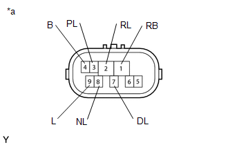
(a) Disconnect the D15 park/neutral position switch assembly connector.
(b) Measure the voltage according to the value(s) in the table below.
Standard Voltage:
| Tester Connection | Switch Condition | Specified Condition |
|---|---|---|
| D15-1 (RB) - Body ground | Engine switch on (IG) | 11 to 14 V |
| D15-1 (RB) - Body ground | Engine switch off | Below 1 V |
| NG | .gif) | REPAIR OR REPLACE HARNESS OR CONNECTOR |
|
.gif)
| 2. | CHECK HARNESS AND CONNECTOR (OUTPUT SIGNAL) |
(a) Disconnect the D15 park/neutral position switch assembly connector.
(b) Measure the voltage according to the value(s) in the table below.
Standard Voltage:
| Tester Connection | Switch Condition | Specified Condition |
|---|---|---|
| D15-4 (B) - Body ground | Engine switch on (IG) | 11 to 14 V |
| D15-4 (B) - Body ground | Engine switch off | Below 1 V |
| NG | | GO TO STEP 6 |
|
| 3. | INSPECT PARK/NEUTRAL POSITION SWITCH ASSEMBLY |
| (a) Disconnect the D15 park/neutral position switch assembly connector. |
|
(b) Measure the resistance according to the value(s) in the table below.
Standard Resistance:
| Tester Connection | Condition | Specified Condition |
|---|---|---|
| 4 (B) - 9 (L) | Shift lever in P or N | Below 1 Ω |
| 1 (RB) - 3 (PL) | Shift lever in P | Below 1 Ω |
| 1 (RB) - 2 (RL) | Shift lever in R | Below 1 Ω |
| 1 (RB) - 8 (NL) | Shift lever in N | Below 1 Ω |
| 1 (RB) - 7 (DL) | Shift lever in D, M, "+" or "-" | Below 1 Ω |
| 4 (B) - 9 (L) | Shift lever not in P or N | 10 kΩ or higher |
| 1 (RB) - 3 (PL) | Shift lever not in P | 10 kΩ or higher |
| 1 (RB) - 2 (RL) | Shift lever not in R | 10 kΩ or higher |
| 1 (RB) - 8 (NL) | Shift lever not in N | 10 kΩ or higher |
| 1 (RB) - 7 (DL) | Shift lever not in D, M, "+" or "-" | 10 kΩ or higher |
| NG | | REPLACE PARK/NEUTRAL POSITION SWITCH ASSEMBLY |
|
| 4. | CHECK HARNESS AND CONNECTOR (PARK/NEUTRAL POSITION SWITCH - ECM) |
(a) Connect the D15 park/neutral position switch assembly connector.
(b) Disconnect the D2 ECM connector.
(c) Turn the engine switch on (IG).
(d) Measure the voltage according to the value(s) in the table below.
Standard Voltage:
| Tester Connection | Condition | Specified Condition |
|---|---|---|
| D2-108 (P) - Body ground |
| 11 to 14 V |
| D2-107 (R) - Body ground |
| 11 to 14 V* |
| D2-140 (N) - Body ground |
| 11 to 14 V |
| D2-139 (D) - Body ground |
| 11 to 14 V |
| D2-108 (P) - Body ground |
| Below 1 V |
| D2-107 (R) - Body ground |
| Below 1 V |
| D2-140 (N) - Body ground |
| Below 1 V |
| D2-139 (D) - Body ground |
| Below 1 V |
HINT:
*: The voltage will drop slightly due to the illumination of the back up lights.
| NG | | REPAIR OR REPLACE HARNESS OR CONNECTOR (PARK/NEUTRAL POSITION SWITCH ASSEMBLY - ECM) |
|
| 5. | REPLACE ECM |
(a) Replace the ECM.
Click here
| NEXT | | PERFORM A/T CODE REGISTRATION |
| 6. | CHECK HARNESS AND CONNECTOR (PARK/NEUTRAL POSITION SWITCH - ECM) |
(a) Disconnect the D15 park/neutral position switch assembly connector.
(b) Disconnect the D2 ECM connector.
(c) Measure the resistance according to the value(s) in the table below.
Standard Resistance:
| Tester Connection | Condition | Specified Condition |
|---|---|---|
| D15-4 (B) - D2-106 (NSW) | Always | Below 1 Ω |
| D15-4 (B) or D2-106 (NSW) - Body ground and other terminals | Always | 10 kΩ or higher |
| NG | | REPAIR OR REPLACE HARNESS OR CONNECTOR (PARK/NEUTRAL POSITION SWITCH ASSEMBLY - ECM) |
|
| 7. | REPLACE ECM |
(a) Replace the ECM.
Click here
| NEXT | | PERFORM A/T CODE REGISTRATION |
 Brake Switch "B" Circuit Short to Battery (P070312)
DESCRIPTION The purpose of the stop light switch signal circuit is to prevent the engine from stalling when the brakes are suddenly applied while driving in the lock-up condition. When the brake pedal ...
 Transmission Fluid Temperature Sensor "A" Circuit Range/Performance (P071000)
DESCRIPTION The ATF temperature sensor converts the automatic transaxle fluid (ATF) temperature into a resistance value for use by the ECM. The ECM applies a voltage to the temperature sensor through ...
Other materials:
Lexus RX (RX 350L, RX450h) 2016-2026 Repair Manual > Audio And Visual System (for 8 Inch Display): Vehicle Speed Signal Circuit between Stereo Component Amplifier and Combination Meter
DESCRIPTION The stereo component amplifier assembly receives a vehicle speed signal from the combination meter assembly to control the ASL function. HINT:
A voltage of 12 V or 5 V is output from each ECU and then input to the combination meter assembly. The signal is changed to a pulse signal at ...
Lexus RX (RX 350L, RX450h) 2016-2026 Repair Manual > Smart Access System With Push-button Start (for Entry Function): Lock Function (Entry Lock Function does not Operate Using Close &)
DESCRIPTION If the back door does not lock when using the power back door close and lock function, there may be communication problem between the certification ECU (smart key ECU assembly) and main body ECU (multiplex network body ECU). CAUTION / NOTICE / HINT NOTICE:
The smart access system with ...
Lexus RX (RX 350L, RX450h) 2016-{YEAR} Owners Manual
- For your information
- Pictorial index
- For safety and security
- Instrument cluster
- Operation of each component
- Driving
- Lexus Display Audio system
- Interior features
- Maintenance and care
- When trouble arises
- Vehicle specifications
- For owners
Lexus RX (RX 350L, RX450h) 2016-{YEAR} Repair Manual

0.0108