Lexus RX (RX 350L, RX450h) 2016-2025 Repair Manual: Intermediate Shaft Speed Sensor "A" Circuit Short to Battery (P079112,P079114,P079131)
DESCRIPTION
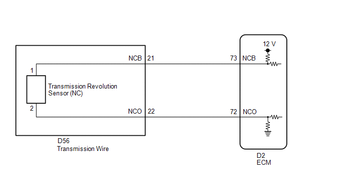
The transmission revolution sensor (NC) detects the rotation speed of the counter gear which shows the output shaft speed of automatic transaxle assembly.
Based on the transmission revolution sensor (NC) signal and the transmission revolution sensor (NT and NC3) signals, the ECM controls engine torque and shift timing.
| DTC No. | Detection Item | DTC Detection Condition | Trouble Area | MIL | Memory | Note |
|---|---|---|---|---|---|---|
| P079112 | Intermediate Shaft Speed Sensor "A" Circuit Short to Battery | 1. Diagnosis Condition 2. Malfunction Status 3. Malfunction Time 4. Other
|
| Comes on | DTC stored | SAE Code P07C6 |
| P079114 | Intermediate Shaft Speed Sensor "A" Circuit Short to Ground or Open | 1. Diagnosis Condition 2. Malfunction Status 3. Malfunction Time 4. Other
|
| Comes on | DTC stored | SAE Code P07C5 |
| P079131 | Intermediate Shaft Speed Sensor "A" No Signal | 1. Diagnosis Condition 2. Malfunction Status 3. Malfunction Time 4. Other
|
| Comes on | DTC stored | SAE Code P0793 |
MONITOR DESCRIPTION
The transmission revolution sensor (NC) monitors the output shaft speed.
The ECM commands gear changes and controls the lock up timing based on the signals from the transmission revolution sensor (NC) and throttle position sensor.
If the vehicle is being driven at 16 km/h (10 mph) or more and the speed sensor (NC) signal sent to the ECM is less than 300 rpm, or if the transmission revolution sensor (NC) input signal voltage is less than 0.1 V or more than 1.9 V, the ECM will illuminate the MIL and store a DTC.
MONITOR STRATEGY
| Related DTCs | P0793: Speed sensor (NC)/Verify pulse input P07C5: Speed sensor (NC)/Range check (Low voltage) P07C6: Speed sensor (NC)/Range check (High voltage) |
| Required sensors/Components | Speed sensor (NT), Speed sensor (NC3), Speed sensor (NC) |
| Frequency of operation | Continuous |
| Duration | P0793: 5 sec. P07C5 and P07C6: 2 sec. |
| MIL operation | Immediate |
| Sequence of operation | None |
TYPICAL ENABLING CONDITIONS
All| Battery voltage | 8 V or more |
| Engine switch | On (IG) |
| Starter | OFF |
| The monitor will run whenever the following DTCs are not present | P07C5, P07C6 (Intermediate shaft speed sensor circuit) U0100 (CAN communication system) P2716 (Pressure control solenoid circuit) |
| Intermediate shaft speed sensor range check fail (P07C5, P07C6) (Pending / MIL) | Not detected |
| Vehicle speed | 16 km/h (9.9 mph) or more |
| Shift change is completed and before starting next shift change operation | - |
| Park/neutral position switch | OFF |
| R range position switch | OFF |
| D range position switch | ON |
| Engine | Running |
| Lost communication with ECM/PCM (U0100) (Pending + MIL) | Not detected |
| Pressure control solenoid circuit fail (P2716) (Pending + MIL) | Not detected |
-
One of the following condition is met: Condition (a), (b), (c), (d), (e), (f), (g) or (h) Condition (a)
Condition (b)ECM selected gear
1st
Turbine Speed Sensor revolution
1830 rpm or more
Condition (c)ECM selected gear
2nd
Turbine Speed Sensor revolution
1060 rpm or more
Condition (d)ECM selected gear
3rd
Turbine Speed Sensor revolution
680 rpm or more
Condition (e)ECM selected gear
4th
Turbine Speed Sensor revolution
510 rpm or more
Condition (f)ECM selected gear
5th
Turbine Speed Sensor revolution
430 rpm or more
Condition (g)ECM selected gear
6th
Turbine Speed Sensor revolution
350 rpm or more
Condition (h)ECM selected gear
7th
Turbine Speed Sensor revolution
300 rpm or more
ECM selected gear
8th
Turbine Speed Sensor revolution
300 rpm or more
| The monitor will run whenever the following DTCs are not stored | P0793 (Intermediate shaft speed sensor verify pulse input) |
| Intermediate shaft speed sensor pulse input fail (P0793) (Pending / MIL) | Not detected |
TYPICAL MALFUNCTION THRESHOLDS
P0793| Intermediate shaft speed sensor revolution | Less than 300 rpm |
| Intermediate shaft speed sensor voltage | Less than 0.1 V |
| Intermediate shaft speed sensor voltage | More than 1.9 V |
COMPONENT OPERATING RANGE
| Intermediate shaft speed sensor revolution | 300 rpm or more |
| Intermediate shaft speed sensor voltage | 0.1 V or more and 1.9 V or less |
CONFIRMATION DRIVING PATTERN
CAUTION:
When performing the confirmation driving pattern, obey all speed limits and traffic laws.
HINT:
- After repairs have been completed, clear the DTCs and then check that the vehicle has returned to normal by performing the following All Readiness check procedure.
-
When clearing the permanent DTCs, refer to the Clear Permanent DTC procedure.
Click here
.gif)
- Connect the Techstream to the DLC3.
- Turn the engine switch on (IG) and turn the Techstream on.
- Clear the DTCs (even if no DTCs are stored, perform the clear DTC procedure).
- Turn the engine switch off and wait for 2 minutes or more.
- Turn the engine switch on (IG) and turn the Techstream on.
- Start the engine.
-
Perform the D Position Shift Test inspection in Road Test. [*1]
Click here
HINT:
[*1] : Normal judgment procedure.
The normal judgment procedure is used to complete DTC judgment and also used when clearing permanent DTCs.
- Enter the following menus: Powertrain / Transmission / Utility / All Readiness.
- Input the DTC: P079112, P079114 or P079131.
-
Check the DTC judgment result.
Techstream Display
Description
NORMAL
- DTC judgment completed
- System normal
ABNORMAL
- DTC judgment completed
- System abnormal
INCOMPLETE
- DTC judgment not completed
- Perform driving pattern after confirming DTC enabling conditions
N/A
- Unable to perform DTC judgment
- Number of DTCs which do not fulfill DTC preconditions has reached ECU memory limit
HINT:
- If the judgment result shows NORMAL, the system is normal.
- If the judgment result shows ABNORMAL, the system has a malfunction.
- If the judgment result shows INCOMPLETE or N/A, perform the normal judgment procedure again.
WIRING DIAGRAM
CAUTION / NOTICE / HINT
NOTICE:
-
Perform the universal trip to clear permanent DTCs.
Click here
-
Perform registration and/or initialization when parts related to the automatic transaxle are replaced.
Click here
DATA LIST
NOTICE:
In the table below, the values listed under "Normal Condition" are reference values. Do not depend solely on these reference values when deciding whether a part is faulty or not.
HINT:
Using the Techstream to read the Data List allows the values or states of switches, sensors, actuators and other items to be read without removing any parts. This non-intrusive inspection can be very useful because intermittent conditions or signals may be discovered before parts or wiring is disturbed. Reading the Data List information early in troubleshooting is one way to save diagnostic time.
(a) Warm up the engine.
(b) Turn the engine switch off.
(c) Connect the Techstream to the DLC3.
(d) Turn the engine switch on (IG).
(e) Turn the Techstream on.
(f) Enter the following menus: Powertrain / Transmission / Data List / NC Sensor Speed.
(g) Read the Data List according to the display on the Techstream.
Powertrain > Transmission > Data List| Tester Display | Measurement Item | Range | Normal Condition | Diagnostic Note |
|---|---|---|---|---|
| NC Sensor Speed | Counter gear speed | Min.: 0 rpm Max.: 12750 rpm | - | - |
| Tester Display |
|---|
| NC Sensor Speed |
HINT:
- NC Sensor Speed is always 0 while driving: Open or short in the sensor or circuit.
- NC Sensor Speed is always more than 0 and less than 300 rpm while driving the vehicle at 16 km/h (10 mph) or more: Sensor malfunction, improper installation, or intermittent connection malfunction in the circuit.
PROCEDURE
| 1. | READ VALUE USING TECHSTREAM (NC SENSOR SPEED AND NC SENSOR VOLTAGE) |
(a) Connect the Techstream to the DLC3.
(b) Turn the engine switch on (IG).
(c) Turn the Techstream on.
(d) Enter the following menus: Powertrain / Transmission / Data List / NC Sensor Speed and NC Sensor Voltage.
(e) Read the Data List according to the display on the Techstream.
Powertrain > Transmission > Data List| Tester Display | Measurement Item | Range | Normal Condition | Diagnostic Note |
|---|---|---|---|---|
| NC Sensor Speed | Counter gear speed | Min.: 0 rpm Max.: 12750 rpm | - | - |
| NC Sensor Voltage | NC sensor voltage | Min.: 0.000 V Max.: 4.999 V | 0.1 to 1.9 V: Engine idling | - |
| Tester Display |
|---|
| NC Sensor Speed |
| NC Sensor Voltage |
| Result | Proceed to |
|---|---|
| Data List value is normal | A |
| Data List value is not normal | B |
| A | .gif) | GO TO STEP 5 |
|
.gif)
| 2. | INSPECT TRANSMISSION REVOLUTION SENSOR (NC) (NC TERMINAL) |
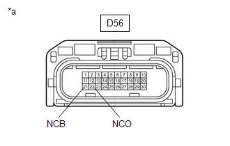
| (a) Disconnect the D56 transmission wire connector. |
|
(b) Measure the resistance according to the value(s) in the table below.
Standard Resistance:
| Tester Connection | Condition | Specified Condition |
|---|---|---|
| D56-22 (NCO) - Body ground | Always | 99 to 101 Ω |
(c) Turn the engine switch on (IG).
(d) Measure the voltage according to the value(s) in the table below.
Standard Voltage:
| Tester Connection | Condition | Specified Condition |
|---|---|---|
| D56-21 (NCB) - Body ground | Engine switch on (IG) | 11 to 14 V |
| NG | | GO TO STEP 4 |
|
| 3. | INSPECT TRANSMISSION WIRE (TRANSMISSION REVOLUTION SENSOR (NC)) |
| (a) Disconnect the transmission revolution sensor (NC) connector. Click here |
|
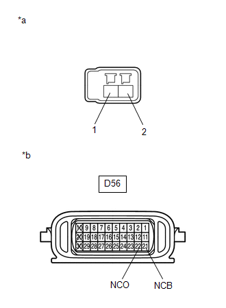
(b) Disconnect the D56 transmission wire connector.
(c) Measure the resistance according to the value(s) in the table below.
Standard Resistance:
| Tester Connection | Condition | Specified Condition |
|---|---|---|
| Transmission revolution sensor (NC) connector terminal 1 - D56-21 (NCB) | Always | Below 1 Ω |
| Transmission revolution sensor (NC) connector terminal 2 - D56-22 (NCO) | Always | Below 1 Ω |
| Transmission revolution sensor (NC) connector terminal 1 or D56-21 (NCB) - Body ground | Always | 10 kΩ or higher |
| Transmission revolution sensor (NC) connector terminal 2 or D56-22 (NCO) - Body ground | Always | 10 kΩ or higher |
| OK | | REPLACE TRANSMISSION REVOLUTION SENSOR (NC) |
| NG | | REPAIR OR REPLACE TRANSMISSION WIRE |
| 4. | CHECK HARNESS AND CONNECTOR (TRANSMISSION WIRE - ECM) |
(a) Disconnect the D56 transmission wire connector.
(b) Disconnect the D2 ECM connector.
(c) Measure the resistance according to the value(s) in the table below.
Standard Resistance:
| Tester Connection | Condition | Specified Condition |
|---|---|---|
| D56-21 (NCB) - D2-73 (NCB) | Always | Below 1 Ω |
| D56-22 (NCO) - D2-72 (NCO) | Always | Below 1 Ω |
| D56-21 (NCB) or D2-73 (NCB) - Body ground | Always | 10 kΩ or higher |
| D56-22 (NCO) or D2-72 (NCO) - Body ground | Always | 10 kΩ or higher |
| NG | | REPAIR OR REPLACE HARNESS OR CONNECTOR (TRANSMISSION WIRE - ECM) |
|
| 5. | REPLACE ECM |
(a) Replace the ECM.
Click here
| NEXT | | PERFORM A/T CODE REGISTRATION |
 Pressure Control Solenoid "B" Actuator Stuck Off (P07757F)
DESCRIPTION Based on signals from the transmission revolution sensors (NT, NC and NC3), the actual gear is detected. The ECM compares the actual gear with the shift schedule in the ECM memory to detec ...
 Pressure Control Solenoid "C" Circuit Open (P079513)
DESCRIPTION Changing gears is performed by the ECM turning the shift solenoid valves SL1, SL2, SL3, SL4 and SL5 on and off. If an open or short occurs in any of the solenoid valve circuits, the ECM co ...
Other materials:
Lexus RX (RX 350L, RX450h) 2016-2025 Repair Manual > Dynamic Torque Control Awd System: Linear Solenoid Circuit (C1298)
DESCRIPTION The 4WD ECU assembly receives signals from each sensor. The signals are used to control the clutch fluid pressure to vary the distribution of torque in accordance with the driving conditions. DTC No. Detection Item DTC Detection Condition Trouble Area C1298 Linear Solenoid ...
Lexus RX (RX 350L, RX450h) 2016-2025 Repair Manual > Navigation System: Visual Mute Signal Circuit between Radio Receiver and Multi-display
DESCRIPTION The radio receiver assembly sends a visual mute signal to the multi-display assembly. As a result, a black screen is displayed when the screen changes so that noise and distorted images are not displayed. When an open exists in the circuit, noise and distorted images will be displayed in ...
Lexus RX (RX 350L, RX450h) 2016-{YEAR} Owners Manual
- For your information
- Pictorial index
- For safety and security
- Instrument cluster
- Operation of each component
- Driving
- Lexus Display Audio system
- Interior features
- Maintenance and care
- When trouble arises
- Vehicle specifications
- For owners
Lexus RX (RX 350L, RX450h) 2016-{YEAR} Repair Manual

0.0194