Lexus RX (RX 350L, RX450h) 2016-2026 Repair Manual: Removal
REMOVAL
CAUTION / NOTICE / HINT
The necessary procedures (adjustment, calibration, initialization or registration) that must be performed after parts are removed and installed, or replaced during shift paddle switch (transmission shift switch assembly) removal/installation are shown below.
Necessary Procedures After Parts Removed/Installed/Replaced| Replacement Part or Performed Procedure | Necessary Procedure | Effect/Inoperative Function when Necessary Procedure not Performed | Link |
|---|---|---|---|
|
*1: When performing learning using the Techstream.
Click here | |||
| Battery terminal is disconnected/reconnected | Memorize steering angle neutral point | Lane Control System | |
| Pre-collision System | |||
| Intelligent Clearance Sonar System*1 | |||
| Lighting System (w/ Automatic Headlight Beam Level Control System) | | ||
| Parking Assist Monitor System | | ||
| Panoramic View Monitor System | | ||
| Initialize back door lock | Power Door Lock Control System | | |
| Reset back door close position | Power Back Door System (w/ Outside Door Control Switch) | | |
PROCEDURE
1. REMOVE STEERING WHEEL ASSEMBLY
Click here .gif)
2. REMOVE CRUISE CONTROL MAIN SWITCH
Click here
3. REMOVE STEERING PAD SWITCH ASSEMBLY
Click here
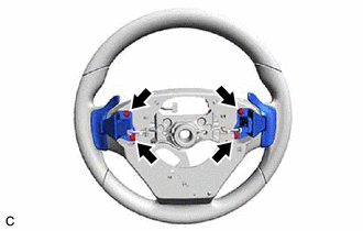
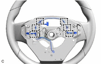
4. REMOVE SHIFT PADDLE SWITCH (TRANSMISSION SHIFT SWITCH ASSEMBLY)
| (a) Remove the 4 screws. |
|
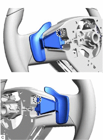
| (b) Disengage the 2 claws and separate the 2 shift paddle switches (transmission shift switch assemblies) from the steering wheel assembly. |
|
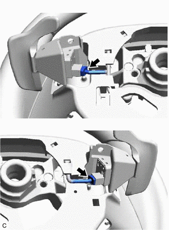
| (c) Disconnect the 2 shift paddle switch (transmission shift switch assembly) connectors to remove the 2 shift paddle switches (transmission shift switch assemblies) from the No. 1 switch wire. |
|
5. REMOVE NO. 1 SWITCH WIRE
HINT:
Perform this procedure only when replacement of the No. 1 switch wire is necessary.
| (a) Disconnect the steering vibration and heater ECU connector. |
|
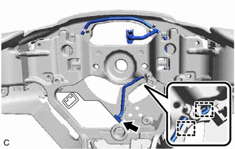
(b) Disengage the 2 guides.
| (c) Disengage the 6 clamps and remove the No. 1 switch wire from the steering wheel assembly. |
|
 Components
COMPONENTS ILLUSTRATION *1 CRUISE CONTROL MAIN SWITCH *2 NO. 1 SWITCH WIRE *3 SHIFT PADDLE SWITCH (TRANSMISSION SHIFT SWITCH ASSEMBLY) *4 STEERING PAD SWITCH ASSEMBLY *5 STEE ...
 Inspection
INSPECTION PROCEDURE 1. INSPECT SHIFT PADDLE SWITCH (TRANSMISSION SHIFT SWITCH ASSEMBLY) (a) Shift Paddle Switch (Transmission Shift Switch Assembly) LH: (1) Measure the resistance according to the ...
Other materials:
Lexus RX (RX 350L, RX450h) 2016-2026 Repair Manual > Navigation System: Data List / Active Test
DATA LIST / ACTIVE TEST DATA LIST NOTICE: In the table below, the values listed under "Normal Condition" are reference values. Do not depend solely on these reference values when deciding whether a part is faulty or not. HINT: Using the Techstream to read the Data List allows the values or states of ...
Lexus RX (RX 350L, RX450h) 2016-2026 Repair Manual > Steering Lock System: Dtc Check / Clear
DTC CHECK / CLEAR NOTICE:
The steering lock ECU (steering lock actuator or upper bracket assembly) does not store history DTCs. If any DTCs are output, confirm and record them as soon as possible. Do not turn the engine switch off or clear the DTCs until the DTCs are confirmed and recorded.
DTC ...
Lexus RX (RX 350L, RX450h) 2016-{YEAR} Owners Manual
- For your information
- Pictorial index
- For safety and security
- Instrument cluster
- Operation of each component
- Driving
- Lexus Display Audio system
- Interior features
- Maintenance and care
- When trouble arises
- Vehicle specifications
- For owners
Lexus RX (RX 350L, RX450h) 2016-{YEAR} Repair Manual

0.0094