Lexus RX (RX 350L, RX450h) 2016-2026 Repair Manual: Removal
REMOVAL
CAUTION / NOTICE / HINT
The necessary procedures (adjustment, calibration, initialization or registration) that must be performed after parts are removed and installed, or replaced during automatic transaxle assembly removal/installation are shown below.
Necessary Procedure After Parts Removed/Installed/Replaced| Replacement Part or Performed Procedure | Necessary Procedure | Effect/Inoperative Function when Necessary Procedure not Performed | Link |
|---|---|---|---|
|
*1: When performing learning using the Techstream.
Click here | |||
| Battery terminal is disconnected/reconnected | Memorize steering angle neutral point | Lane Control System | |
| Pre-collision System | |||
| Intelligent Clearance Sonar System*1 | |||
| Lighting System (w/ Automatic Headlight Beam Level Control System) | | ||
| Parking Assist Monitor System | | ||
| Panoramic View Monitor System | | ||
| Initialize back door lock | Power Door Lock Control System | | |
| Reset back door close position | Power Back Door System (w/ Outside Door Control Switch) | | |
| Replacement of automatic transaxle assembly | Perform the following procedures in the order shown:
|
| |
| Replacement of ECM (If possible, read the transaxle compensation code from the previous ECM) | Perform the following procedures in the order shown:
| ||
| Replacement of ECM (If impossible, read the transaxle compensation code from the previous ECM) | Perform the following procedures in the order shown:
| ||
| Front wheel alignment adjustment | Calibration |
| |
| Suspension, tires, etc. (The vehicle height changes because of suspension or tire replacement) |
|
| |
| Rear television camera assembly optical axis (Back camera position setting) | Parking Assist Monitor System | | |
| Panoramic View Monitor System | | |
| Initialize No. 1 headlight ECU sub-assembly LH | Lighting System (w/ Automatic Headlight Beam Level Control System) | | |
| Replacement of throttle body with motor assembly | Inspection After Repair |
| |
| Cleaning the deposits from the throttle body with motor assembly | |||
| Air leaks from intake system is repaired | |||
| Gas leak from exhaust system is repaired | |||
| Replacement of ECM | Vehicle Identification Number (VIN) registration | MIL comes on | |
| ECU communication ID registration (Immobiliser system) | Engine start function | | |
| Perform code registration (Immobiliser system) |
| | |
CAUTION:
The automatic transaxle assembly is very heavy. Be sure to follow the procedure described in the repair manual, or the transmission jack may suddenly drop.
.png)
| *a | Object Exceeding Weight Limit of Transmission Jack |
NOTICE:
If automatic transaxle parts are replaced, refer to Parts Replacement Compensation Table to determine if any additional operations are necessary.
Click here .gif)
PROCEDURE
1. PRECAUTION
NOTICE:
After turning the engine switch off, waiting time may be required before disconnecting the cable from the negative (-) battery terminal. Therefore, make sure to read the disconnecting the cable from the negative (-) battery terminal notices before proceeding with work.
Click here
2. DISCONNECT CABLE FROM NEGATIVE BATTERY TERMINAL
NOTICE:
When disconnecting the cable, some systems need to be initialized after the cable is reconnected.
Click here
3. REMOVE V-BANK COVER SUB-ASSEMBLY
Click here
4. REMOVE FRONT WIPER MOTOR AND LINK ASSEMBLY
Click here
5. REMOVE OUTER COWL TOP PANEL SUB-ASSEMBLY
Click here
6. REMOVE STARTER ASSEMBLY
Click here
7. REMOVE ECM
Click here
8. REMOVE BATTERY
Click here
9. REMOVE BATTERY CARRIER SUB-ASSEMBLY
| (a) Disengage the 2 clamps. |
|
.png)
(b) Remove the 6 bolts and battery carrier sub-assembly from the vehicle body.
10. REMOVE BATTERY BRACKET REINFORCEMENT
| (a) Remove the 2 bolts and battery bracket reinforcement from the vehicle body. |
|
.png)
11. DISCONNECT TRANSMISSION CONTROL CABLE ASSEMBLY
Click here
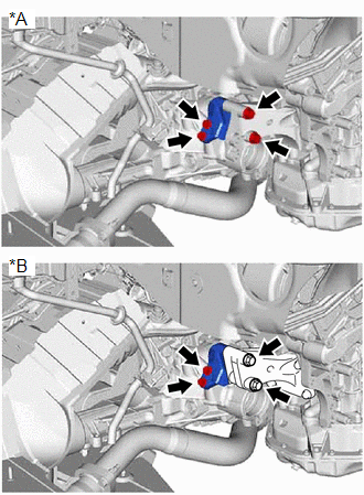
12. REMOVE NO. 2 VACUUM SWITCHING VALVE ASSEMBLY
Click here
13. DISCONNECT WIRE HARNESS
| (a) Disconnect the transmission wire connector and park/neutral position switch assembly connector. |
|
.png)
(b) Remove the bolt and disconnect the wire harness from the automatic transaxle case sub-assembly.
14. REMOVE FRONT STABILIZER BAR
Click here
15. REMOVE FRONT WHEEL OPENING EXTENSION PAD LH
Click here
16. REMOVE NO. 3 ENGINE UNDER COVER
Click here
17. REMOVE SUSPENSION TOWER DAMPER (w/ Suspension Tower Damper)
Click here
18. REMOVE FRONT LOWER BUMPER ABSORBER
Click here
19. REMOVE FRONT FENDER APRON SEAL LH
Click here
20. REMOVE FRONT DRIVE SHAFT ASSEMBLY
Click here
21. REMOVE PROPELLER WITH CENTER BEARING SHAFT ASSEMBLY
Click here
22. REMOVE NO. 1 EXHAUST PIPE SUPPORT BRACKET (for Lower Side)
Click here
23. REMOVE FRONT EXHAUST PIPE ASSEMBLY
Click here
24. REMOVE NO. 1 EXHAUST PIPE SUPPORT BRACKET
Click here
25. DRAIN ENGINE COOLANT
Click here
26. DISCONNECT NO. 1 RADIATOR HOSE
Click here
27. DISCONNECT VENTILATION HOSE
Click here
28. DISCONNECT PURGE VALVE (PURGE VSV) (for TMMC Made)
Click here
29. DISCONNECT PURGE VALVE (PURGE VSV) (except TMMC Made)
Click here
30. REMOVE NO. 2 SURGE TANK STAY
Click here
31. REMOVE INTAKE AIR SURGE TANK ASSEMBLY
Click here
32. REMOVE AIR SURGE TANK TO INTAKE MANIFOLD GASKET
Click here
33. REMOVE WIRE HARNESS CLAMP BRACKET
| (a) Disconnect the air fuel ratio sensor (for Bank 1) connector. |
|
.png)
| (b) Disengage the hose clamp and 3 wire harness clamps. |
|
.png)
(c) Remove the bolt and wire harness clamp bracket from the cylinder head RH.
34. REMOVE FUEL PUMP PROTECTOR
Click here
35. INSTALL ENGINE HANGER
| (a) Install the No. 1 engine hanger to the cylinder head RH with the bolt. Torque: 43 N·m {438 kgf·cm, 32 ft·lbf}
|
|
.png)
(b) Install the No. 2 engine hanger to the cylinder head LH with the 2 bolts.
Torque:
33 N·m {337 kgf·cm, 24 ft·lbf}
| Item | Part No. |
|---|---|
| No. 2 Engine Hanger | 12282-31100 |
| Bolt | 91671-10825 |
36. INSTALL ENGINE SUPPORT BRIDGE
(a) Install SST to the vehicle body as shown in the illustration.
.png)
| *a | Support Shaft | *b | Front Side Member |
| *c | Cloth | *d | Front Side |
| *e | Front Suspension Nut | - | - |
SST: 09940-10020
CAUTION:
-
Make sure that no oil or grease is on the front side member, and set the support shaft on the level surface of the front side member.
.png)
*a
Support Shaft
*b
Front Side Member
- The engine support bridge may fall off if any oil or grease is still on or it is installed on the unlevel surface.
NOTICE:
- Prevent SST from contacting the vehicle body exterior and windshield glass.
- To prevent damage to the engine hood, place pieces of cloth between the engine hood and SST.
- Lightly shake SST by hand to make sure it is securely installed before performing work.
| (b) Turn the threaded portion of each support shaft to adjust its height until the sub beams are parallel to the ground. |
|
.png)
(c) Install the chain block to the sling bracket.
.png)
| *a | Chain Block | *b | Sling Bracket |
| *c | Fuse Shackle | *d | Shackle (A) |
(d) Install the division bar to the chain block with the shackles.
CAUTION:
-
Make sure the fuse shackle is on the chain block side and the shackle (A) is on the division bar side as shown in the illustration so that the fuse bolt is visible and can be checked for deformation easily.
.png)
*a
Fuse Shackle
*b
Shackle (A)
- If the fuse shackle is installed upside down, deformation of the fuse bolt will not be visible and cannot be used to tell if the load capacity of the engine support bridge has been exceeded. If the load capacity is exceeded, it may cause the engine support bridge to damage the vehicle and the engine assembly with automatic transaxle assembly may fall.
-
Make sure that the fuse bolt of the fuse shackle is free of damage, such as deformation or cracks. If damaged, replace the fuse shackle.
.png)
*a
Fuse Shackle
*b
Fuse Bolt
- If a deformed fuse bolt is used, it cannot be used to tell if the load capacity of the engine support bridge has been exceeded. If the load capacity is exceeded, it may cause the engine support bridge to damage the vehicle and the engine assembly with transaxle assembly may fall.
(e) Connect the division bar to the No. 1 engine hanger with the 2 shackles (A).
.png)
| *1 | No. 1 Engine Hanger | *2 | No. 2 Engine Hanger |
| *a | Division Bar | *b | Shackle (A) |
| *c | Chain | - | - |
(f) Connect the division bar to the No. 2 engine hanger with the shackle (A) and chain.
NOTICE:
Connect the 2nd link of the chain to the No. 2 engine hanger.
(g) Make sure the distance between the chain block assembly and suspension ring is 120 mm (4.72 in.) or more.
.png)
| *a | Chain Block Assembly | *b | Suspension Ring |
| *c | 120 mm (4.72 in.) or more | - | - |
HINT:
If the suspension height is less than 120 mm, adjust the links of the chain which connect the division bar and engine hanger.
(h) Adjust the position of the support bracket LH and RH so that the length of dimension (A) and (B) are 240 mm (9.45 in.) as shown in the illustration.
.png)
| *a | Support Bracket LH | *b | Support Bracket RH |
| *c | Dimension (A): 240 mm (9.45 in.) | *d | Dimension (B): 240 mm (9.45 in.) |
| *e | Sub Beam | - | - |
.png) | Front of Vehicle | - | - |
(i) Adjust the positions of the chain block assembly, support brackets and main beam so that the chain of the chain block assembly is perpendicular to the main beam and the length of the main beam on the outer side of the support bracket LH and RH is the same as shown in the illustration.
.png)
| *a | Chain Block Assembly | *b | Main Beam |
| *c | Dimension (C) | *d | Dimension (D) |
| *e | Right to Left Adjustment | - | - |
CAUTION:
- To prevent the engine with automatic transaxle assembly from falling, make sure that the length of dimension (C) and dimension (D) are equal.
-
Do not perform any procedures if the length of dimension (C) and dimension (D) are not equal.
.png)
*a
Main Beam
- Performing any procedure when the length of dimension (C) and dimension (D) are not equal may cause the engine assembly with automatic transaxle assembly and engine support bridge to fall, possibly causing serious injury.
(j) Confirm the appropriate installation state of the engine support bridge and tighten the 6 wing bolts and 2 bolts.
.png)
| *a | Wing Bolt | *b | Bolt |
Torque:
Bolt :
30 N·m {306 kgf·cm, 22 ft·lbf}
CAUTION:
-
Do not perform any procedures before tightening the bolts to the specified torque.
.png)
- Performing procedures without tightening the bolts to the specified torque, may cause the engine support bridge to fall.
(k) Tighten the chain block assembly until it cannot be moved any further by hand.
.png)
| *a | Turn |
.png)
| *a | 41 N*m (418 kgf*cm, 30 ft.*lbf) or more |
- When suspending the engine with automatic transaxle assembly, do not tighten the chain block assembly more than 41 N*m (418 kgf*cm, 30 ft.*lbf).
- Tightening the chain block assembly more than 41 N*m (418 kgf*cm, 30 ft.*lbf) will cause the load capacity (400 kg (881.8 lb)) to be exceeded and may cause damage to the engine support bridge and vehicle body.
37. REMOVE FLYWHEEL HOUSING UNDER COVER
| (a) Remove the 2 bolts and flywheel housing under cover from the automatic transaxle case sub-assembly. |
|
.png)
38. REMOVE DRIVE PLATE AND TORQUE CONVERTER ASSEMBLY SETTING BOLT
| (a) Turn the crankshaft to gain access to the 6 drive plate and torque converter assembly setting bolts and remove each drive plate and torque converter assembly setting bolt while holding the crankshaft pulley bolt with a wrench. HINT: There will be one black colored drive plate and torque converter assembly setting bolt. |
|
.png)
39. SEPARATE FRONT ENGINE MOUNTING INSULATOR
Click here
40. SEPARATE REAR ENGINE MOUNTING INSULATOR
Click here
41. REMOVE FRONT FRAME ASSEMBLY
Click here
42. REMOVE TRANSFER STIFFENER PLATE RH
| (a) Remove the 4 bolts and transfer stiffener plate RH from the transfer case sub-assembly and No. 2 transfer stiffener plate. |
|
43. DISCONNECT NO. 1 TRANSMISSION OIL COOLER HOSE
Click here
44. REMOVE FRONT ENGINE MOUNTING INSULATOR
Click here
45. REMOVE FRONT ENGINE MOUNTING BRACKET
| (a) Remove the 3 bolts and front engine mounting bracket from the transaxle housing. |
|
.png)
46. REMOVE ENGINE MOUNTING INSULATOR LH
| (a) Disengage the clamp. |
|
.png)
(b) Remove the nut and separate the engine wire from the engine mounting insulator LH.
| (c) Remove the nut and through bolt. |
|
.png)
| (d) Remove the 5 bolts and engine mounting insulator LH from the vehicle body. |
|
.png)
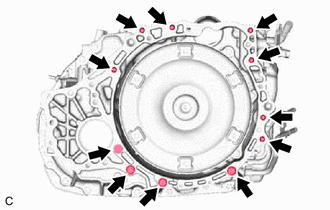
47. REMOVE AUTOMATIC TRANSAXLE ASSEMBLY
(a) Support the automatic transaxle assembly with a transmission jack.
NOTICE:
Secure the automatic transaxle assembly to the transmission jack using a suitable adapter, such as a rope or attachment.
| (b) Remove the 11 bolts and automatic transaxle assembly. NOTICE: To prevent damage to the knock pins, do not pry between the automatic transaxle assembly and engine assembly. |
|
48. REMOVE TRANSFER ASSEMBLY
Click here
49. REMOVE ENGINE MOUNTING BRACKET LH
| (a) Disengage the transmission breather clamp from the engine mounting bracket LH. |
|
.png)
| (b) Remove the 4 bolts and engine mounting bracket LH from the automatic transaxle case sub-assembly. |
|
.png)
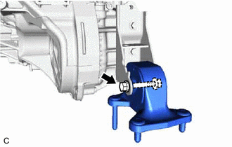
50. REMOVE REAR ENGINE MOUNTING INSULATOR
| (a) Remove the through bolt and rear engine mounting insulator from the rear engine mounting bracket. |
|
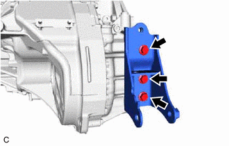
51. REMOVE REAR ENGINE MOUNTING BRACKET
| (a) Remove the 3 bolts and rear engine mounting bracket from the transaxle housing. |
|
52. REMOVE NO. 2 TRANSMISSION CONTROL CABLE BRACKET
| (a) Remove the bolt and No. 2 transmission control cable bracket from the automatic transaxle case sub-assembly. |
|
.png)
53. REMOVE TRANSMISSION BREATHER SKIRT
| (a) Disengage the 3 clamps to separate the transmission breather plug. |
|
.png)
(b) Remove the bolt and transmission breather skirt from the automatic transaxle case sub-assembly.
54. REMOVE TORQUE CONVERTER ASSEMBLY
(a) Remove the torque converter assembly from the automatic transaxle assembly.
55. INSPECT TORQUE CONVERTER ASSEMBLY
Click here
56. INSPECT DRIVE PLATE AND RING GEAR SUB-ASSEMBLY
Click here
 Installation
INSTALLATION PROCEDURE 1. INSTALL TORQUE CONVERTER ASSEMBLY (a) Turn the front oil pump drive gear so that either key is at the top and place a matchmark on the transaxle housing to indicate the po ...

Other materials:
Lexus RX (RX 350L, RX450h) 2016-2026 Repair Manual > Occupant Classification System: Lost Communication with Multi-axis Acceleration Sensor Module (U0125,U0129)
DESCRIPTION The occupant detection ECU sends/receives signals to/from each ECU via CAN communication. DTC No. Detection Item DTC Detection Condition Trouble Area U0125 Lost Communication with Multi-axis Acceleration Sensor Module CAN communication error between the occupant detectio ...
Lexus RX (RX 350L, RX450h) 2016-2026 Repair Manual > Automatic Transaxle System: Diagnosis System
DIAGNOSIS SYSTEM DESCRIPTION (a) When troubleshooting On-Board Diagnostic (OBD II) vehicles, an OBD II scan tool (complying with SAE J1978) must be connected to the vehicle. Various data output from the vehicle ECM can then be read. (b) OBD II regulations require that the vehicle on-board computer i ...
Lexus RX (RX 350L, RX450h) 2016-{YEAR} Owners Manual
- For your information
- Pictorial index
- For safety and security
- Instrument cluster
- Operation of each component
- Driving
- Lexus Display Audio system
- Interior features
- Maintenance and care
- When trouble arises
- Vehicle specifications
- For owners
Lexus RX (RX 350L, RX450h) 2016-{YEAR} Repair Manual

0.0097