Lexus RX (RX 350L, RX450h) 2016-2026 Repair Manual: Pressure Control Solenoid "A" Circuit Open (P074513)
DESCRIPTION
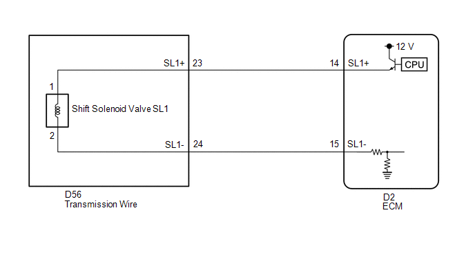
Changing gears is performed by the ECM turning the shift solenoid valves SL1, SL2, SL3, SL4 and SL5 on and off.
If an open or short occurs in any of the shift solenoid valve circuits, the ECM controls the remaining normal shift solenoid valves to allow the vehicle to be driven. If all of the shift solenoid valves are malfunctioning, only the mechanical fluid pressure circuit will function and some manual operation will be possible. If an open or short occurs in a shift solenoid valve circuit, the ECM cuts power to the malfunctioning shift solenoid valve.
HINT:
The following table shows normal operation of the shift solenoid valve SL1 when the shift lever is in D.
Shift Solenoid Valve Operation:| Gear | 1st | 2nd | 3rd | 4th | 5th | 6th | 7th | 8th |
|---|---|---|---|---|---|---|---|---|
| Shift Solenoid Valve SL1 | ON | ON | ON | ON | ON | OFF | OFF | OFF |
| DTC No. | Detection Item | DTC Detection Condition | Trouble Area | MIL | Memory | Note |
|---|---|---|---|---|---|---|
| P074513 | Pressure Control Solenoid "A" Circuit Open | 1. Diagnosis Condition 2. Malfunction Status 3. Malfunction Time 4. Other
|
| Comes on | DTC stored | SAE Code: P0748 |
MONITOR DESCRIPTION
This DTC indicates an open or short in the shift solenoid valve SL1 circuit. The ECM commands gear shifts by turning the shift solenoid valves on or off. When there is an open or short in any shift solenoid valve circuit, the ECM detects the problem, illuminates the MIL and stores a DTC.
The ECM performs the fail-safe function and turns the other normal shift solenoid valves on or off. In the case of an open or short circuit, the ECM stops sending current to the open or shorted solenoid.
MONITOR STRATEGY
| Related DTCs | P0748: Shift solenoid valve SL1/Range check |
| Required sensors/Components | Shift solenoid valve SL1 |
| Frequency of operation | Continuous |
| Duration | 1 sec. |
| MIL operation | Immediate |
| Sequence of operation | None |
TYPICAL ENABLING CONDITIONS
All| The monitor will run whenever the following DTCs are not present | None |
| Solenoid current cut status | Not cut |
| Engine switch | On (IG) |
| Starter | OFF |
| Battery voltage | 12 V or more |
| Battery voltage | 10 V or more and less than 12 V |
| Target current | Less than 0.75 A |
| Battery voltage | 8 V or more |
| Target current | 0.25 A or more |
TYPICAL MALFUNCTION THRESHOLDS
When one of the following conditions is met: Condition (A), (B) or (C)
Condition (A) and (B)| Output duty cycle | 100% or more |
| Output duty cycle | 0% or less |
COMPONENT OPERATING RANGE
| Output duty cycle | More than 3% and less than 100% |
CONFIRMATION DRIVING PATTERN
CAUTION:
When performing the confirmation driving pattern, obey all speed limits and traffic laws.
HINT:
- After repairs have been completed, clear the DTCs and then check that the vehicle has returned to normal by performing the following All Readiness check procedure.
-
When clearing the permanent DTCs, refer to the Clear Permanent DTC procedure.
Click here
.gif)
- Connect the Techstream to the DLC3.
- Turn the engine switch on (IG) and turn the Techstream on.
- Clear the DTCs (even if no DTCs are stored, perform the clear DTC procedure).
- Turn the engine switch off and wait for 2 minutes or more.
- Turn the engine switch on (IG) and turn the Techstream on.
- Start the engine.
-
Perform the D Position Shift Test inspection in Road Test. [*1]
Click here
HINT:
[*1] : Normal judgment procedure.
The normal judgment procedure is used to complete DTC judgment and also used when clearing permanent DTCs.
- Enter the following menus: Powertrain / Transmission / Utility / All Readiness.
- Input the DTC: P074513.
-
Check the DTC judgment result.
Techstream Display
Description
NORMAL
- DTC judgment completed
- System normal
ABNORMAL
- DTC judgment completed
- System abnormal
INCOMPLETE
- DTC judgment not completed
- Perform driving pattern after confirming DTC enabling conditions
N/A
- Unable to perform DTC judgment
- Number of DTCs which do not fulfill DTC preconditions has reached ECU memory limit
HINT:
- If the judgment result shows NORMAL, the system is normal.
- If the judgment result shows ABNORMAL, the system has a malfunction.
- If the judgment result shows INCOMPLETE or N/A, perform the normal judgment procedure again.
WIRING DIAGRAM
CAUTION / NOTICE / HINT
NOTICE:
-
Perform the universal trip to clear permanent DTCs.
Click here
-
Perform registration and/or initialization when parts related to the automatic transaxle are replaced.
Click here
PROCEDURE
| 1. | CHECK HARNESS AND TRANSMISSION WIRE (TRANSMISSION WIRE (SHIFT SOLENOID VALVE SL1) - ECM) |
(a) Disconnect the D2 ECM connector.
(b) Measure the resistance according to the value(s) in the table below.
Standard Resistance:
| Tester Connection | Condition | Specified Condition |
|---|---|---|
| D2-14 (SL1+) - D2-15 (SL1-) | 20°C (68°F) | 5.0 to 5.6 Ω |
| D2-14 (SL1+) or D2-15 (SL1-) - Body ground and other terminals | Always | 10 kΩ or higher |
| NG | .gif) | GO TO STEP 3 |
|
.gif)
| 2. | REPLACE ECM |
(a) Replace the ECM.
Click here
| NEXT | | PERFORM A/T CODE REGISTRATION |
| 3. | CHECK HARNESS AND CONNECTOR (TRANSMISSION WIRE - ECM) |
(a) Disconnect the D56 transmission wire connector.
(b) Disconnect the D2 ECM connector.
(c) Measure the resistance according to the value(s) in the table below.
Standard Resistance:
| Tester Connection | Condition | Specified Condition |
|---|---|---|
| D56-23 (SL1+) - D2-14 (SL1+) | Always | Below 1 Ω |
| D56-24 (SL1-) - D2-15 (SL1-) | Always | Below 1 Ω |
| D56-23 (SL1+) or D2-14 (SL1+) - Body ground and other terminals | Always | 10 kΩ or higher |
| D56-24 (SL1-) or D2-15 (SL1-) - Body ground and other terminals | Always | 10 kΩ or higher |
| NG | | REPAIR OR REPLACE HARNESS OR CONNECTOR (TRANSMISSION WIRE - ECM) |
|
| 4. | INSPECT SHIFT SOLENOID VALVE SL1 |
| (a) Remove the shift solenoid valve SL1. Click here |
|
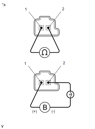
(b) Measure the resistance according to the value(s) in the table below.
Standard Resistance:
| Tester Connection | Condition | Specified Condition |
|---|---|---|
| Shift solenoid valve SL1 connector terminal 1 - terminal 2 | 20°C (68°F) | 5.0 to 5.6 Ω |
(c) Connect a positive (+) lead from the battery to terminal 1 and a negative (-) lead with a 21 W bulb to terminal 2 of the solenoid valve connector. Check that the valve moves and makes an operating sound.
OK:
Valve moves and makes an operating sound.
| OK | | REPAIR OR REPLACE TRANSMISSION WIRE |
| NG | | REPLACE SHIFT SOLENOID VALVE SL1 |
 Input/Turbine Speed Sensor "A" Circuit Short to Battery (P071512,P071514,P071531)
DESCRIPTION The transmission revolution sensor (NT) detects the input shaft rotation speed and sends it to the ECM. Based on the transmission revolution sensor (NT) signal and the transmission revolut ...
 Pressure Control Solenoid "A" Actuator Stuck Off (P07457F)
DESCRIPTION Based on signals from the transmission revolution sensors (NT, NC3 and NC), the actual gear is detected. The ECM compares the actual gear with the shift schedule in the ECM memory to detec ...
Other materials:
Lexus RX (RX 350L, RX450h) 2016-2026 Repair Manual > Sfi System: Low Pressure Fuel System Pressure - Too Low (P008A00)
DESCRIPTION In order to supply the optimal fuel pressure according to the driving conditions and usage environment, the variable fuel system sends a drive signal from the ECM to the fuel pump control ECU assembly, steplessly performing variable control of the fuel pump (for low pressure side) and re ...
Lexus RX (RX 350L, RX450h) 2016-2026 Repair Manual > Power Mirror Control System (w/ Memory): Power Mirrors do not Return to Memorized Position
DESCRIPTION If any of the M1, M2 or M3 seat memory switch is pressed, the outer mirror control ECU assembly (driver door) detects the switch operation and sends the seat memory switch signal to the main body ECU (multiplex network body ECU) via CAN communication. The main body ECU (multiplex network ...
Lexus RX (RX 350L, RX450h) 2016-{YEAR} Owners Manual
- For your information
- Pictorial index
- For safety and security
- Instrument cluster
- Operation of each component
- Driving
- Lexus Display Audio system
- Interior features
- Maintenance and care
- When trouble arises
- Vehicle specifications
- For owners
Lexus RX (RX 350L, RX450h) 2016-{YEAR} Repair Manual

0.0105