Lexus RX (RX 350L, RX450h) 2016-2025 Repair Manual: Input/Turbine Speed Sensor "B" Circuit Short to Battery (P276512,P276514,P276531)
DESCRIPTION
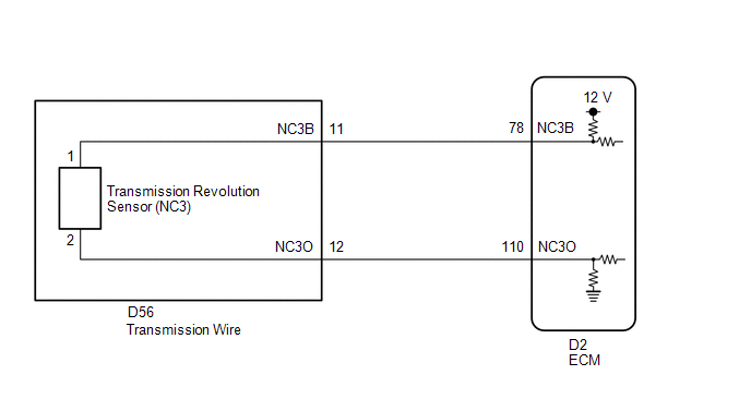
The transmission revolution sensor (NC3) detects the automatic transmission No. 3 clutch drum rotation speed.
| DTC No. | Detection Item | DTC Detection Condition | Trouble Area | MIL | Memory | Note |
|---|---|---|---|---|---|---|
| P276512 | Input/Turbine Speed Sensor "B" Circuit Short to Battery | 1. Diagnosis Condition 2. Malfunction Status 3. Malfunction Time 4. Other
|
| Comes on | DTC stored | SAE Code: P07C2 |
| P276514 | Input/Turbine Speed Sensor "B" Circuit Short to Ground or Open | 1. Diagnosis Condition 2. Malfunction Status 3. Malfunction Time 4. Other
|
| Comes on | DTC stored | SAE Code: P07C1 |
| P276531 | Input/Turbine Speed Sensor "B" No Signal | 1. Diagnosis Condition 2. Malfunction Status 3. Malfunction Time 4. Other
|
| Comes on | DTC stored | SAE Code: P2767 |
MONITOR DESCRIPTION
The NC3O terminal of the ECM detects a pulse signal from the transmission revolution sensor (NC3) (input RPM). The ECM calculates gear shifts by comparing the transmission revolution sensor (NT) with the transmission revolution sensor (NC3 and NC).
While the vehicle is being driven with the shift lever in D, if the input shaft speed is less than 300 rpm* when the turbine speed is 830 rpm or more and intermediate shaft speed is 950 rpm or more, the ECM determines there is a malfunction, illuminates the MIL and stores a DTC.
*: Pulse is not output or is irregularly output.
MONITOR STRATEGY
| Related DTCs | P07C1, P07C2: Speed sensor (NC3)/Range check P2767: Speed sensor (NC3)/Verify pulse input |
| Required sensors/Components | Speed sensor (NC), Speed sensor (NT), Speed sensor (NC3) |
| Frequency of operation | Continuous |
| Duration | P07C1, P07C2: 4.5 sec. P2767: 5 sec. |
| MIL operation | Immediate |
| Sequence of operation | None |
TYPICAL ENABLING CONDITIONS
P07C1, P07C2| The monitor will run whenever the following DTCs are not present | P2767 (Input speed sensor verify pulse input) |
| Battery voltage | 8 V or more |
| Engine switch | On (IG) |
| Starter | OFF |
| Input speed sensor pulse input fail (P2767) (Pending / MIL) | Not detected |
| The monitor will run whenever the following DTCs are not present | P07C1, P07C2 (Input speed sensor circuit) P0746, P0748, P0776, P0778, P0796, P0798, P2716, P2808, P2810, P2817, P2819 (Pressure control solenoid circuit) P0751, P0752, P0973, P0974 (Shift solenoid circuit) |
| Battery voltage | 8 V or more |
| Engine switch | On (IG) |
| Starter | OFF |
| Input speed sensor range check fail (P07C1, P07C2) (Pending / MIL) | Not detected |
| Turbine speed sensor revolution | 830 rpm or more |
| Intermediate shaft speed sensor revolution | 950 rpm or more |
| NC3 monitor status | Enable |
| Park/neutral position switch | OFF |
| R range position switch | OFF |
| D range position switch | ON |
| Pressure control solenoid circuit fail (P0746, P0748, P0776, P0778, P0796, P0798, P2716, P2808, P2810, P2817, P2819) (Pending + MIL) | Not detected |
| Shift solenoid circuit fail (P0751, P0752, P0973, P0974) (Pending + MIL) | Not detected |
TYPICAL MALFUNCTION THRESHOLDS
P07C1| Input speed sensor voltage | Less than 0.1 V |
| Input speed sensor voltage | More than 1.9 V |
| Input speed sensor revolution | Less than 300 rpm |
COMPONENT OPERATING RANGE
| Input Speed Sensor voltage | 0.1 V or more and 1.9 V or less |
| Input Speed Sensor revolution | 300 rpm or more |
CONFIRMATION DRIVING PATTERN
CAUTION:
When performing the confirmation driving pattern, obey all speed limits and traffic laws.
HINT:
- After repairs have been completed, clear the DTCs and then check that the vehicle has returned to normal by performing the following All Readiness check procedure.
-
When clearing the permanent DTCs, refer to the Clear Permanent DTC procedure.
Click here
.gif)
- Connect the Techstream to the DLC3.
- Turn the engine switch on (IG) and turn the Techstream on.
- Clear the DTCs (even if no DTCs are stored, perform the clear DTC procedure).
- Turn the engine switch off and wait for 2 minutes or more.
- Turn the engine switch on (IG) and turn the Techstream on.
- Start the engine.
-
Perform the D Position Shift Test inspection in Road Test. [*1]
Click here
HINT:
[*1] : Normal judgment procedure.
The normal judgment procedure is used to complete DTC judgment and also used when clearing permanent DTCs.
- Enter the following menus: Powertrain / Transmission / Utility / All Readiness.
- Input the DTC: P276512, P276514 or P276531.
-
Check the DTC judgment result.
Techstream Display
Description
NORMAL
- DTC judgment completed
- System normal
ABNORMAL
- DTC judgment completed
- System abnormal
INCOMPLETE
- DTC judgment not completed
- Perform driving pattern after confirming DTC enabling conditions
N/A
- Unable to perform DTC judgment
- Number of DTCs which do not fulfill DTC preconditions has reached ECU memory limit
HINT:
- If the judgment result shows NORMAL, the system is normal.
- If the judgment result shows ABNORMAL, the system has a malfunction.
- If the judgment result shows INCOMPLETE or N/A, perform the normal judgment procedure again.
WIRING DIAGRAM
CAUTION / NOTICE / HINT
NOTICE:
-
Perform the universal trip to clear permanent DTCs.
Click here
-
Perform registration and/or initialization when parts related to the automatic transaxle are replaced.
Click here
DATA LIST
NOTICE:
In the table below, the values listed under "Normal Condition" are reference values. Do not depend solely on these reference values when deciding whether a part is faulty or not.
HINT:
Using the Techstream to read the Data List allows the values or states of switches, sensors, actuators and other items to be read without removing any parts. This non-intrusive inspection can be very useful because intermittent conditions or signals may be discovered before parts or wiring is disturbed. Reading the Data List information early in troubleshooting is one way to save diagnostic time.
(a) Warm up the engine.
(b) Turn the engine switch off.
(c) Connect the Techstream to the DLC3.
(d) Turn the engine switch on (IG).
(e) Turn the Techstream on.
(f) Enter the following menus: Powertrain / Transmission / Data List / NC3 Sensor Speed.
(g) Read the Data List according to the display on the Techstream.
Powertrain > Transmission > Data List| Tester Display | Measurement Item | Range | Normal Condition | Diagnostic Note |
|---|---|---|---|---|
| NC3 Sensor Speed | No. 3 clutch drum speed | Min.: 0 rpm Max.: 12750 rpm |
| Data is displayed in increments of 50 rpm |
| Tester Display |
|---|
| NC3 Sensor Speed |
HINT:
- NC3 Sensor Speed is always 0 while driving: Open or short in the sensor or circuit.
- NC3 Sensor Speed is always more than 0 and less than 300 rpm while driving the vehicle at 50 km/h (31 mph) or more: Sensor malfunction, improper installation, or intermittent connection malfunction of the circuit.
PROCEDURE
| 1. | READ VALUE USING TECHSTREAM |
(a) Connect the Techstream to the DLC3.
(b) Turn the engine switch on (IG).
(c) Turn the Techstream on.
(d) Enter the following menus: Powertrain / Transmission / Data List / NC3 Sensor voltage, NC3 Sensor Speed.
(e) Read the Data List according to the display on the Techstream.
Powertrain > Transmission > Data List| Tester Display | Measurement Item | Range | Normal Condition | Diagnostic Note |
|---|---|---|---|---|
| NC3 Sensor Voltage | NC3 Sensor Voltage | Min.: 0.000 V Max.: 4.999 V | 0.1 to 1.9 V: Engine idling | - |
| NC3 Sensor Speed | No. 3 clutch drum speed | Min.: 0 rpm Max.: 12750 rpm |
| Data is displayed in increments of 50 rpm |
| Tester Display |
|---|
| NC3 Sensor Voltage |
| NC3 Sensor Speed |
| Result | Proceed to |
|---|---|
| Data List value is normal | A |
| Data List value is not normal | B |
| A | .gif) | GO TO STEP 5 |
|
.gif)
| 2. | INSPECT TRANSMISSION REVOLUTION SENSOR (NC3) (NC3 TERMINAL) |
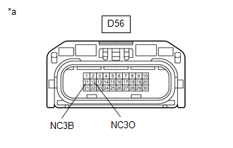
| (a) Disconnect the D56 transmission wire connector. |
|
(b) Measure the resistance according to the value(s) in the table below.
Standard Resistance:
| Tester Connection | Condition | Specified Condition |
|---|---|---|
| D56-12 (NC3O) - Body ground | Always | 99 to 101 Ω |
(c) Turn the engine switch on (IG).
(d) Measure the voltage according to the value(s) in the table below.
Standard Voltage:
| Tester Connection | Condition | Specified Condition |
|---|---|---|
| D56-11 (NC3B) - Body ground | Engine switch on (IG) | 11 to 14 V |
| NG | | GO TO STEP 4 |
|
| 3. | INSPECT TRANSMISSION WIRE (TRANSMISSION REVOLUTION SENSOR (NC3)) |
| (a) Disconnect the transmission revolution sensor (NC3) connector. Click here |
|
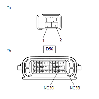
(b) Disconnect the D56 transmission wire connector.
(c) Measure the resistance according to the value(s) in the table below.
Standard Resistance:
| Tester Connection | Condition | Specified Condition |
|---|---|---|
| Transmission revolution sensor (NC3) connector terminal 1 - D56-11 (NC3B) | Always | Below 1 Ω |
| Transmission revolution sensor (NC3) connector terminal 2 - D56-12 (NC3O) | Always | Below 1 Ω |
| Transmission revolution sensor (NC3) connector terminal 1 or D56-11 (NC3B) - Body ground | Always | 10 kΩ or higher |
| Transmission revolution sensor (NC3) connector terminal 2 or D56-12 (NC3O) - Body ground | Always | 10 kΩ or higher |
| OK | | REPLACE TRANSMISSION REVOLUTION SENSOR (NC3) |
| NG | | REPAIR OR REPLACE TRANSMISSION WIRE |
| 4. | CHECK HARNESS AND CONNECTOR (TRANSMISSION WIRE - ECM) |
(a) Disconnect the D56 transmission wire connector.
(b) Disconnect the D2 ECM connector.
(c) Measure the resistance according to the value(s) in the table below.
Standard Resistance:
| Tester Connection | Condition | Specified Condition |
|---|---|---|
| D56-11 (NC3B) - D2-78 (NC3B) | Always | Below 1 Ω |
| D56-12 (NC3O) - D2-110 (NC3O) | Always | Below 1 Ω |
| D56-11 (NC3B) or D2-78 (NC3B) - Body ground | Always | 10 kΩ or higher |
| D56-12 (NC3O) or D2-110 (NC3O) - Body ground | Always | 10 kΩ or higher |
| NG | | REPAIR OR REPLACE HARNESS OR CONNECTOR (TRANSMISSION WIRE - ECM) |
|
| 5. | REPLACE ECM |
(a) Replace the ECM.
Click here
| NEXT | | PERFORM A/T CODE REGISTRATION |
 Torque Converter Clutch Pressure Control Solenoid Control Actuator Stuck Off (P27567F)
DESCRIPTION The ECM controls the shift solenoid valve SLU using a predetermined current, and performs lock-up and flex lock-up control. The ECM compares the engagement condition of the lock-up clutch ...
 Pressure Control Solenoid "G" Circuit Open (P280713)
DESCRIPTION Changing gears is performed by the ECM turning the shift solenoid valves SL1, SL2, SL3, SL4 and SL5 on and off. If an open or short occurs in any of the shift solenoid valve circuits, the ...
Other materials:
Lexus RX (RX 350L, RX450h) 2016-2025 Repair Manual > Theft Deterrent System: Power Source Circuit
DESCRIPTION Based on changes in the power source voltage, the main body ECU (multiplex network body ECU) can detect if the battery has been disconnected and reconnected. WIRING DIAGRAM CAUTION / NOTICE / HINT NOTICE:
Before replacing the main body ECU (multiplex network body ECU), refer to Regis ...
Lexus RX (RX 350L, RX450h) 2016-2025 Owners Manual > For safe use: For safe driving
For safe driving, adjust the seat and mirror to an appropriate position
before
driving.
Correct driving posture
Adjust the angle of the seatback so
that you are sitting straight up and so
that you do not have to lean forward
to steer.
Adjust the seat so that you can
depress the pe ...
Lexus RX (RX 350L, RX450h) 2016-{YEAR} Owners Manual
- For your information
- Pictorial index
- For safety and security
- Instrument cluster
- Operation of each component
- Driving
- Lexus Display Audio system
- Interior features
- Maintenance and care
- When trouble arises
- Vehicle specifications
- For owners
Lexus RX (RX 350L, RX450h) 2016-{YEAR} Repair Manual

0.0191