Lexus RX (RX 350L, RX450h) 2016-2025 Repair Manual: Torque Converter Clutch Pressure Control Solenoid Control Actuator Stuck Off (P27567F)
DESCRIPTION
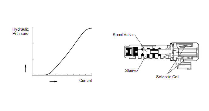
The ECM controls the shift solenoid valve SLU using a predetermined current, and performs lock-up and flex lock-up control.
The ECM compares the engagement condition of the lock-up clutch with the lock-up schedule in the ECM memory to detect mechanical malfunctions of the shift solenoid valve SLU, transmission valve body assembly and torque converter assembly.
| DTC No. | Detection Item | DTC Detection Condition | Trouble Area | MIL | Memory | Note |
|---|---|---|---|---|---|---|
| P27567F | Torque Converter Clutch Pressure Control Solenoid Control Actuator Stuck Off | 1. Diagnosis Condition 2. Malfunction Status 3. Malfunction Time 4. Other SLU stuck ON malfunction:
SLU stuck OFF malfunction:
|
| Comes on | DTC stored | SAE Code: P2757 |
MONITOR DESCRIPTION
Torque converter lock-up is controlled by the ECM based on the transmission revolution sensor (NT, NC), engine speed, engine load, engine temperature, vehicle speed, ATF temperature and gear selection signals. The ECM determines the lock-up status of the torque converter assembly by comparing the engine speed (NE) to the transmission revolution sensor (NT) signal. The ECM calculates the actual gear by comparing the transmission revolution sensor (NT) signal to the transmission revolution sensor (NC) signal. When conditions are appropriate, the ECM requests "lock-up" by applying voltage to the shift solenoid valve SLU. When the shift solenoid valve SLU is turned on, pressure is applied to the lock-up relay valve and locks the torque converter assembly.
If the ECM does not detect lock-up after lock-up has been requested or if it detects lock-up when it is not requested, it interprets this as a malfunction of the shift solenoid valve SLU, illuminates the MIL and stores this DTC.
HINT:
Example:
When any of the following is met, the system judges it as a malfunction.
- There is a difference in speed between the input side (engine speed) and output side (input turbine speed) of the torque converter assembly when the ECM commands lock-up. (Engine speed is at least 70 rpm more than input turbine speed.)
- There is no difference in speed between the input side (engine speed) and output side (input turbine speed) of the torque converter assembly when the ECM commands lock-up off. (The difference between engine speed and input turbine speed is less than 35 rpm.)
MONITOR STRATEGY
| Related DTCs | P2757: Shift solenoid valve SLU/OFF malfunction |
| Required sensors/Components | Shift solenoid valve SLU |
| Frequency of operation | Continuous |
| Duration | OFF malfunction: 3.5 sec. ON malfunction: 1.8 sec. |
| MIL operation | 2 driving cycles |
| Sequence of operation | None |
TYPICAL ENABLING CONDITIONS
All| The monitor will run whenever this DTC is not present. (Not circuit malfunction) | P0717, P07BF, P07C0 (Turbine speed sensor circuit) P0793, P07C5, P07C6 (Intermediate shaft speed sensor circuit) P0335, P0337, P0338 (Crankshaft Position Sensor "A" circuit) (This condition applies only if using fail-safe) P0748 (Shift solenoid valve SL1 circuit) P0778 (Shift solenoid valve SL2 circuit) P0798 (Shift solenoid valve SL3 circuit) P2810 (Shift solenoid valve SL4 circuit) P2819 (Shift solenoid valve SL5 circuit) P0973, P0974 (Shift solenoid valve S1 circuit) P0712, P0713 (ATF temperature sensor circuit (TFT sensor)) P2759 (Shift solenoid valve SLU circuit) P0115, P0117, P0118 (ECT sensor circuit) P0327, P0328, P032C, P032D, P0332, P0333, P033C, P033D (KCS sensor circuit) P0120, P0121, P0122, P0123, P0220, P0222, P0223, P0604, P0606, P0607, P060A, P060B, P060D, P060E, P0657, P1607, P2102, P2103, P2111, P2112, P2118, P2119, P2135 ((ETCS) Electronic throttle control system) U0100 (CAN communication system) |
| NSW switch | "D" and "not R" and "not N" |
| Duration time from shifting "N" to "D" | 4 sec. or more |
| ATF temperature | -10°C (14°F) or more |
| Engine | Starting |
| ECT | 40°C (104°F) or more |
| Spark advance from MAX. retard timing by KCS control | 0 °CA or more |
| TCM selected gear | Not 1st |
| Vehicle speed | 25 km/h (15.62 mph) or more |
| TCM selected gear and transaxle actual gear | Match |
-
When either condition below is met: Condition (1) or (2)
-
Condition (1)
When one of the following conditions is met: Condition (a), (b), (c), (d), (e), (f), (g) or (h)
Condition (a)
Condition (b)Turbine speed / Output speed (NT / NO)
(Actual 1st gear)
4.197 or more and 8.529 or less
(when output speed less than 130 rpm)
Condition (c)Turbine speed / Output speed (NT / NO)
(Actual 2nd gear)
2.599 or more and 3.108 or less
(when output speed less than 200 rpm)
Condition (d)Turbine speed / Output speed (NT / NO)
(Actual 3rd gear)
1.712 or more and 1.962 or less
(when output speed less than 400 rpm)
Condition (e)Turbine speed / Output speed (NT / NO)
(Actual 4th gear)
1.289 or more and 1.455 or less
(when output speed less than 600 rpm)
Condition (f)Turbine speed / Output speed (NT / NO)
(Actual 5th gear)
1.064 or more and 1.233 or less
(when output speed less than 600 rpm)
Condition (g)Turbine speed / Output speed (NT / NO)
(Actual 6th gear)
0.88 or more and 1.004 or less
(when output speed less than 800 rpm)
Condition (h)Turbine speed / Output speed (NT / NO)
(Actual 7th gear)
0.701 or more and 0.825 or less
(when output speed less than 800 rpm)
Turbine speed / Output speed (NT / NO)
(Actual 8th gear)
0.585 or more and 0.683 or less
(when output speed less than 1000 rpm)
-
Condition (2)
When all of the following conditions are met: Condition (a), (b), (c), (d), (e), (f), (g) and (h)
Condition (a)
Condition (b)Turbine speed - Output speed x 1st gear ratio
(Actual 1st gear)
-50 rpm or more and 50 rpm or less
(when output speed 130 rpm or more)
Condition (c)Turbine speed - Output speed x 2nd gear ratio
(Actual 2nd gear)
-50 rpm or more and 50 rpm or less
(when output speed 200 rpm or more)
Condition (d)Turbine speed - Output speed x 3rd gear ratio
(Actual 3rd gear)
-50 rpm or more and 50 rpm or less
(when output speed 400 rpm or more)
Condition (e)Turbine speed - Output speed x 4th gear ratio
(Actual 4th gear)
-50 rpm or more and 50 rpm or less
(when output speed 600 rpm or more)
Condition (f)Turbine speed - Output speed x 5th gear ratio
(Actual 5th gear)
-50 rpm or more and 50 rpm or less
(when output speed 600 rpm or more)
Condition (g)Turbine speed - Output speed x 6th gear ratio
(Actual 6th gear)
-50 rpm or more and 50 rpm or less
(when output speed 800 rpm or more)
Condition (h)Turbine speed - Output speed x 7th gear ratio
(Actual 7th gear)
-50 rpm or more and 50 rpm or less
(when output speed 800 rpm or more)
Turbine speed - Output speed x 8th gear ratio
(Actual 8th gear)
-50 rpm or more and 50 rpm or less
(when output speed 1000 rpm or more)
-
Condition (1)
| TCM indicated pressure value of SLU | 715 kPa (7.3 kgf/cm2, 104 psi) or more |
| TCM indicated S1 solenoid | OFF |
| TCM indicated S2 solenoid | OFF |
| TCM indicated pressure value of SLU | Less than 4 kPa (0.04 kgf/cm2, 0.6 psi) |
| Throttle valve opening angle | 7% or more at turbine speed 3000 rpm (conditions vary with turbine speed) |
| Vehicle speed | Less than 60 km/h (37.5 mph) |
| Calculated load value | 23.25% or more at turbine speed 3000 rpm (conditions vary with turbine speed) |
TYPICAL MALFUNCTION THRESHOLDS
OFF malfunction| Engine Speed - Turbine speed | 70 rpm or more |
| Engine Speed - Turbine speed | Less than 35 rpm |
CONFIRMATION DRIVING PATTERN
CAUTION:
When performing the confirmation driving pattern, obey all speed limits and traffic laws.
HINT:
- After repairs have been completed, clear the DTCs and then check that the vehicle has returned to normal by performing the following All Readiness check procedure.
-
When clearing the permanent DTCs, refer to the Clear Permanent DTC procedure.
Click here
.gif)
- Connect the Techstream to the DLC3.
- Turn the engine switch on (IG) and turn the Techstream on.
- Clear the DTCs (even if no DTCs are stored, perform the clear DTC procedure).
- Turn the engine switch off and wait for 2 minutes or more.
- Turn the engine switch on (IG) and turn the Techstream on.
- Start the engine.
-
Perform the Lock-up Function inspection in Road Test. [*1]
Click here
HINT:
[*1] : Normal judgment procedure.
The normal judgment procedure is used to complete DTC judgment and also used when clearing permanent DTCs.
- Enter the following menus: Powertrain / Transmission / Utility / All Readiness.
- Input the DTC: P27567F.
-
Check the DTC judgment result.
Techstream Display
Description
NORMAL
- DTC judgment completed
- System normal
ABNORMAL
- DTC judgment completed
- System abnormal
INCOMPLETE
- DTC judgment not completed
- Perform driving pattern after confirming DTC enabling conditions
N/A
- Unable to perform DTC judgment
- Number of DTCs which do not fulfill DTC preconditions has reached ECU memory limit
HINT:
- If the judgment result shows NORMAL, the system is normal.
- If the judgment result shows ABNORMAL, the system has a malfunction.
- If the judgment result shows INCOMPLETE or N/A, perform the normal judgment procedure again.
CAUTION / NOTICE / HINT
NOTICE:
-
Perform the universal trip to clear permanent DTCs.
Click here
-
Perform registration and/or initialization when parts related to the automatic transaxle are replaced.
Click here
PROCEDURE
| 1. | CHECK DTC OUTPUT (IN ADDITION TO DTC P27567F) |
(a) Connect the Techstream to the DLC3.
(b) Turn the engine switch on (IG).
(c) Turn the Techstream on.
(d) Enter the following menus: Powertrain / Transmission / Trouble Codes.
Powertrain > Transmission > Trouble Codes(e) Read the DTCs using the Techstream.
| Result | Proceed to |
|---|---|
| Only DTC P27567F is output | A |
| DTC P27567F and other DTCs are output | B |
HINT:
- If any DTCs other than P27567F are output, perform troubleshooting for those DTCs first.
- If a shift solenoid valve is stuck ON or OFF, DTCs for several shift solenoid valves including the malfunctioning shift solenoid valve will be stored.
| B | .gif) | GO TO DTC CHART |
|
.gif)
| 2. | INSPECT SHIFT SOLENOID VALVE SLU |
| (a) Remove the shift solenoid valve SLU. Click here |
|
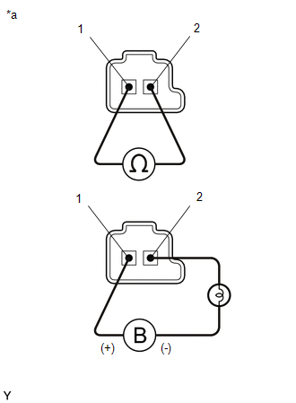
(b) Measure the resistance according to the value(s) in the table below.
Standard Resistance:
| Tester Connection | Condition | Specified Condition |
|---|---|---|
| Shift solenoid valve SLU connector terminal 1 - Terminal 2 | 20°C (68°F) | 5.0 to 5.6 Ω |
(c) Connect a positive (+) lead from the battery to terminal 1 and a negative (-) lead with a 21 W bulb to terminal 2 of the solenoid valve connector. Check that the valve moves and makes an operating sound.
OK:
Valve moves and makes an operating sound.
| NG | | REPLACE SHIFT SOLENOID VALVE SLU |
|
| 3. | INSPECT TRANSMISSION VALVE BODY ASSEMBLY |
(a) Inspect the transmission valve body assembly.
Click here
OK:
There is no foreign matter on each valve and they operate smoothly.
| NG | | REPAIR OR REPLACE TRANSMISSION VALVE BODY ASSEMBLY |
|
| 4. | INSPECT TORQUE CONVERTER ASSEMBLY |
(a) Inspect the torque converter assembly.
Click here
OK:
The torque converter assembly is normal.
| NG | | REPAIR OR REPLACE TORQUE CONVERTER ASSEMBLY |
|
| 5. | REPAIR OR REPLACE AUTOMATIC TRANSAXLE ASSEMBLY |
(a) Repair or replace the automatic transaxle assembly.
Click here
| NEXT | | PERFORM A/T CODE REGISTRATION |
 Torque Converter Clutch Pressure Control Solenoid Control Circuit Open (P275613)
DESCRIPTION The ECM controls the shift solenoid valve SLU using a predetermined current, and performs lock-up and flex lock-up control. DTC No. Detection Item DTC Detection Condition Trouble ...
 Input/Turbine Speed Sensor "B" Circuit Short to Battery (P276512,P276514,P276531)
DESCRIPTION The transmission revolution sensor (NC3) detects the automatic transmission No. 3 clutch drum rotation speed. DTC No. Detection Item DTC Detection Condition Trouble Area MIL M ...
Other materials:
Lexus RX (RX 350L, RX450h) 2016-2025 Repair Manual > Name Plate: Removal
REMOVAL CAUTION / NOTICE / HINT HINT: When removing the name plates, heat the vehicle body and name plates using a heat light. Heating Temperature Item Temperature Vehicle Body 40 to 60°C (104 to 140°F) Name Plate 20 to 30°C (68 to 86°F) CAUTION:
Do not touch the heat ligh ...
Lexus RX (RX 350L, RX450h) 2016-2025 Repair Manual > Power Seat Switch(for Rear Side): Components
COMPONENTS ILLUSTRATION *A for 60/40 Split Seat Type RH Side - - *1 POWER SEAT SWITCH ASSEMBLY *2 REAR POWER SEAT SWITCH RH *3 RECLINING REMOTE CONTROL BEZEL RH - - ILLUSTRATION *A for 60/40 Split Seat Type LH Side - - *1 POWER SEAT SWITCH ASSEMBLY ...
Lexus RX (RX 350L, RX450h) 2016-{YEAR} Owners Manual
- For your information
- Pictorial index
- For safety and security
- Instrument cluster
- Operation of each component
- Driving
- Lexus Display Audio system
- Interior features
- Maintenance and care
- When trouble arises
- Vehicle specifications
- For owners
Lexus RX (RX 350L, RX450h) 2016-{YEAR} Repair Manual

0.0193