Lexus RX (RX 350L, RX450h) 2016-2026 Repair Manual: Disassembly
DISASSEMBLY
PROCEDURE
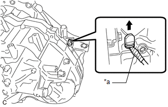
1. REMOVE BREATHER PLUG HOSE
| (a) Using a screwdriver with its tip wrapped with protective tape, remove the breather plug hose from the breather plug. NOTICE: Be careful not to damage the breather plug. |
|
.png)
| (b) Using a screwdriver with its tip wrapped with protective tape, remove the No. 1 breather plug (ATM) from the breather plug hose. NOTICE: Be careful not to damage the No. 1 breather plug (ATM). |
|
.png)
(c) Remove the breather hose clamp and transmission breather clamp from the breather plug hose.
2. REMOVE TRANSMISSION CONTROL SHAFT LEVER
| (a) Remove the nut and transmission control shaft lever from the manual valve lever sub-assembly. |
|
.png)
3. REMOVE PARK/NEUTRAL POSITION SWITCH ASSEMBLY
| (a) Using a screwdriver, bend back the tabs of the lock plate and remove the lock nut and lock plate from the park/neutral position switch assembly. |
|
.png)
| (b) Remove the 2 bolts and park/neutral position switch assembly from the automatic transaxle case sub-assembly. |
|
.png)
4. REMOVE DRAIN PLUG
| (a) Using a T40 "TORX" socket wrench, remove the drain plug from the overflow plug. |
|
.png)
(b) Remove the O-ring from the drain plug.
5. REMOVE OVERFLOW PLUG
| (a) Using a 17 mm straight hexagon wrench, remove the overflow plug from the transaxle housing. |
|
.png)
| (b) Remove the O-ring from the overflow plug. |
|
.png)
6. REMOVE OUTLET NO. 1 OIL COOLER TUBE SUB-ASSEMBLY
| (a) Remove the 2 bolts and outlet No. 1 oil cooler tube sub-assembly from the transaxle housing. |
|
.png)
| (b) Remove the O-ring from the outlet No. 1 oil cooler tube sub-assembly. |
|
.png)
7. REMOVE INLET NO. 1 OIL COOLER TUBE SUB-ASSEMBLY
| (a) Remove the 2 bolts and inlet No. 1 oil cooler tube sub-assembly from the transaxle housing. |
|
.png)
| (b) Remove the O-ring from the inlet No. 1 oil cooler tube sub-assembly. |
|
.png)
8. REMOVE REFILL PLUG
| (a) Remove the refill plug from the automatic transaxle case sub-assembly. |
|
.png)
(b) Remove the gasket from the refill plug.
9. REMOVE TRANSMISSION CASE PLUG ASSEMBLY
| (a) Using a screwdriver with its tip wrapped with protective tape, remove the transmission case plug assembly from the transaxle housing. NOTICE: Be careful not to damage the transaxle housing. |
|
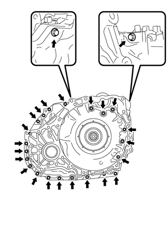
10. REMOVE TRANSAXLE SIDE COVER SUB-ASSEMBLY
| (a) Using a T40 "TORX" socket wrench, remove the 13 bolts. |
|
.png)
| (b) Insert the blade of an oil pan seal cutter between the transaxle side cover sub-assembly and automatic transaxle case sub-assembly. Cut through the applied seal packing and remove the transaxle side cover sub-assembly. NOTICE: Be careful not to damage the sealing surface of the automatic transaxle case sub-assembly. |
|
.png)
11. REMOVE TRANSMISSION OIL CLEANER MAGNET
| (a) Remove the 2 transmission oil cleaner magnets from the transaxle side cover sub-assembly. |
|
.png)
12. REMOVE TRANSMISSION VALVE BODY ASSEMBLY
Click here .gif)
13. REMOVE TRANSMISSION WIRE
Click here
14. REMOVE TRANSMISSION REVOLUTION SENSOR (NC3)
Click here
15. REMOVE TRANSMISSION REVOLUTION SENSOR (NT)
Click here
16. INSPECT INPUT SHAFT END PLAY
Click here
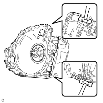
17. REMOVE TRANSAXLE HOUSING
| (a) Remove the 24 bolts. |
|
| (b) Using a plastic hammer, tap on the circumference of the transaxle housing to remove it from the automatic transaxle case sub-assembly. |
|
18. REMOVE DIFFERENTIAL GEAR LUBE APPLY TUBE
| (a) Remove the bolt and clamp from the transaxle housing. |
|
.png)
| (b) Remove the differential gear lube apply tube from the transaxle housing. |
|
.png)
19. REMOVE TRANSAXLE HOUSING OIL SEPARATOR
| (a) Remove the 2 bolts and transaxle housing oil separator from the transaxle housing. |
|
.png)
| (b) Remove the 3 transmission oil cleaner magnets from the transaxle housing oil separator. |
|
.png)
20. INSPECT TRANSMISSION OIL CLEANER MAGNET
Click here
21. REMOVE DIFFERENTIAL CASE TAPERED ROLLER BEARING (FRONT SIDE OUTER RACE)
| (a) Using SST, remove the differential case tapered roller bearing (front side outer race) from the transaxle housing. SST: 09308-00010 |
|
.png)
22. REMOVE TRANSAXLE CASE OIL SEAL
| (a) Using SST and a hammer, remove the transaxle case oil seal from the transaxle housing. SST: 09950-60010 09951-00550 SST: 09950-70010 09951-07200 |
|
.png)
23. REMOVE COUNTER DRIVEN GEAR TAPERED ROLLER BEARING (FRONT SIDE OUTER RACE)
| (a) Using a screwdriver with its tip wrapped with protective tape, pry up the counter driven gear tapered roller bearing (front side outer race). NOTICE: Be careful not to damage the transaxle housing. |
|
.png)
| (b) Using SST, remove the counter driven gear tapered roller bearing (front side outer race) from the transaxle housing. SST: 09308-36010 |
|
.png)
24. INSPECT B-1 BRAKE PISTON ROD STROKE
Click here
25. REMOVE FRONT OIL PUMP ASSEMBLY
| (a) Remove the 3 transaxle case gaskets from the front oil pump assembly. |
|
.png)
| (b) Remove the front oil pump body O-ring from the front oil pump assembly. |
|
.png)
| (c) Remove the 7 bolts and front oil pump assembly from the automatic transaxle case sub-assembly. |
|
.png)
| (d) Remove the planetary carrier thrust washer from the front oil pump assembly. |
|
.png)
26. REMOVE NO. 1 GOVERNOR APPLY GASKET
| (a) Remove the No. 1 governor apply gasket from the automatic transaxle case sub-assembly. |
|
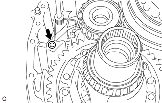
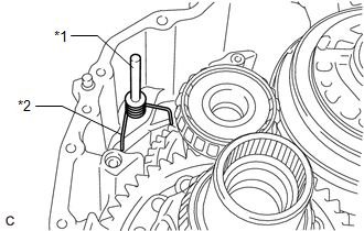
27. REMOVE MANUAL DETENT SPRING SUB-ASSEMBLY
| (a) Remove the bolt, manual detent spring cover and manual detent spring sub-assembly from the automatic transaxle case sub-assembly. |
|
.png)
28. REMOVE PARKING LOCK ROD SUB-ASSEMBLY
| (a) Remove the bolt, spring guide sleeve and torsion spring from the automatic transaxle case sub-assembly. |
|
.png)
| (b) Remove the bolt and parking lock pawl bracket from the automatic transaxle case sub-assembly. |
|
.png)
| (c) Remove the parking lock rod sub-assembly from the manual valve lever sub-assembly. HINT: Align the slot with the notches on the manual valve lever sub-assembly to remove the parking lock rod sub-assembly. |
|
.png)
29. REMOVE PARKING LOCK PAWL
| (a) Remove the parking lock pawl shaft and torsion spring from the automatic transaxle case sub-assembly. |
|
| (b) Remove the parking lock pawl from the automatic transaxle case sub-assembly. |
|
.png)
30. REMOVE PARKING LOCK PIN SUB-ASSEMBLY
| (a) Remove the parking lock pin sub-assembly from the automatic transaxle case sub-assembly. |
|
.png)
31. REMOVE MANUAL VALVE LEVER SUB-ASSEMBLY
| (a) Remove the manual valve lever sub-assembly from the automatic transaxle case sub-assembly. |
|
.png)
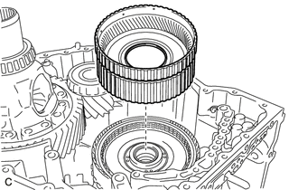
32. REMOVE C-3 AND C-4 CLUTCH ASSEMBLY
| (a) Remove the bolt from the automatic transaxle case sub-assembly. |
|
.png)
| (b) Remove the B-1 brake band assembly from the C-3 and C-4 clutch drum. |
|
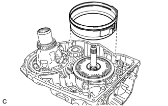
| (c) Remove the C-3 and C-4 clutch assembly with front planetary gear assembly from the automatic transaxle case sub-assembly. |
|
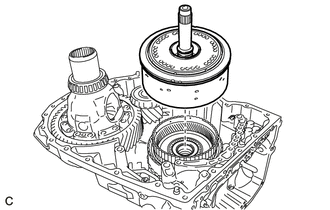
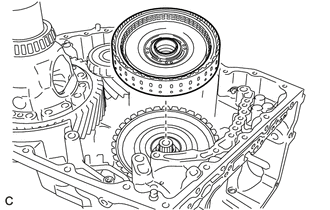
| (d) Remove the C-3 and C-4 clutch assembly from the front planetary gear assembly. |
|
.png)
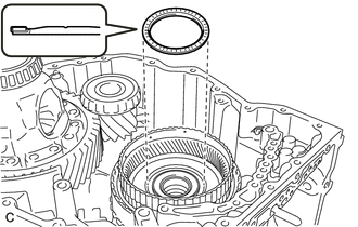
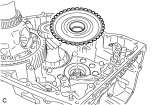
33. REMOVE FRONT PLANETARY GEAR ASSEMBLY
| (a) Remove the No. 2 planetary carrier thrust washer and No. 7 thrust bearing race from the front planetary gear assembly. |
|
.png)
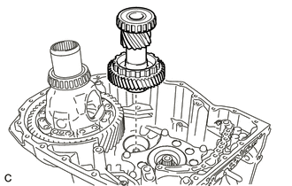
| (b) Remove the planetary sun gear from the front planetary gear assembly. |
|
.png)
| (c) Remove the No. 9 thrust bearing race, thrust needle roller bearing and No. 8 thrust bearing race from the front planetary gear assembly. |
|
.png)
| (d) Remove the 2 rear input shaft oil seal rings from the front planetary gear assembly. |
|
.png)
| (e) Remove the 4 input shaft oil seal rings from the front planetary gear assembly. |
|
.png)
| (f) Remove the needle roller bearing from the front planetary gear assembly. |
|
.png)
34. INSPECT FRONT PLANETARY GEAR ASSEMBLY
Click here
35. REMOVE FRONT PLANETARY RING GEAR
| (a) Remove the thrust needle roller bearing from the front planetary ring gear flange. |
|
| (b) Remove the front planetary ring gear with front planetary ring gear flange from the C-1 clutch assembly. |
|
| (c) Using a screwdriver with its tip wrapped with protective tape, remove the snap ring from the front planetary ring gear. NOTICE: Be careful not to damage the front planetary ring gear. |
|
.png)
| (d) Remove the front planetary ring gear flange from the front planetary ring gear. |
|
.png)
36. REMOVE C-1 CLUTCH ASSEMBLY
| (a) Remove the thrust needle roller bearing and No. 6 thrust bearing race from the C-1 clutch assembly. |
|
.png)
| (b) Remove the C-1 clutch assembly from the rear planetary sun gear sub-assembly. |
|
37. INSPECT CLEARANCE OF C-1 CLUTCH
Click here
38. REMOVE FORWARD MULTIPLE DISC CLUTCH DISC
| (a) Using a screwdriver with its tip wrapped with protective tape, remove the snap ring from the clutch drum sub-assembly. NOTICE: Be careful not to damage the clutch drum sub-assembly. |
|
.png)
| (b) Remove the forward clutch flange, 5 forward multiple disc clutch discs and 5 forward multiple disc clutch plates from the clutch drum sub-assembly. |
|
.png)
39. INSPECT FORWARD MULTIPLE DISC CLUTCH DISC
Click here
40. REMOVE NO. 1 CLUTCH BALANCER
| (a) Place SST on the No. 1 clutch balancer and compress the forward clutch return spring sub-assembly with a press. SST: 09387-00020 |
|
.png)
(b) Using a snap ring expander, remove the snap ring from the clutch drum sub-assembly.
NOTICE:
Do not expand the snap ring excessively.
| (c) Remove the No. 1 clutch balancer from the clutch drum sub-assembly. |
|
.png)
41. REMOVE FORWARD CLUTCH RETURN SPRING SUB-ASSEMBLY
.png)
(a) Remove the forward clutch return spring sub-assembly from the clutch drum sub-assembly.
42. INSPECT FORWARD CLUTCH RETURN SPRING SUB-ASSEMBLY
Click here
43. REMOVE FORWARD CLUTCH PISTON
| (a) Cover the ATF hole shown in the illustration and apply compressed air (approximately 392 kPa (4.0 kgf/cm2, 57 psi)) to the ATF hole. |
|
.png)
| (b) Remove the forward clutch piston from the clutch drum sub-assembly. |
|
.png)
| (c) Remove the O-ring from the forward clutch piston. |
|
.png)
44. REMOVE C-1 DRUM O-RING
| (a) Remove the 2 C-1 drum O-rings from the clutch drum sub-assembly. |
|
.png)
45. REMOVE INPUT SUN GEAR DRUM
| (a) Remove the thrust needle roller bearing and No. 5 thrust bearing race from the input sun gear drum. |
|
.png)
| (b) Remove the input sun gear drum from the rear planetary gear assembly. |
|
46. REMOVE PINION AND COUNTER DRIVEN GEAR SUB-ASSEMBLY
| (a) Remove the pinion and counter driven gear sub-assembly from the automatic transaxle case sub-assembly. |
|
47. REMOVE COUNTER DRIVEN GEAR TAPERED ROLLER BEARING (FRONT SIDE INNER RACE)
| (a) Using SST and a press, remove the counter driven gear tapered roller bearing (front side inner race) from the pinion and counter driven gear sub-assembly. SST: 09950-00020 SST: 09950-60010 09951-00400 SST: 09950-70010 09951-07100 |
|
.png)
48. REMOVE COUNTER DRIVEN GEAR TAPERED ROLLER BEARING (REAR SIDE INNER RACE)
| (a) Using SST, remove the counter driven gear tapered roller bearing (rear side inner race) from the pinion and counter driven gear sub-assembly. SST: 09950-40011 09951-04010 09952-04010 09953-04030 09954-04010 09955-04061 09957-04010 09958-04011 SST: 09950-60010 09951-00320 |
|
.png)
49. REMOVE TIGHT PLUG (COUNTER DRIVEN GEAR SIDE)
| (a) Using a screwdriver with its tip wrapped with protective tape, remove the tight plug (counter driven gear side) from the pinion and counter driven gear sub-assembly. NOTICE: Be careful not to damage the pinion and counter driven gear sub-assembly. |
|
.png)
50. REMOVE TIGHT PLUG (DIFFERENTIAL DRIVEN PINION SIDE)
| (a) Using a brass bar and a hammer, remove the tight plug (differential drive pinion side) from the pinion and counter driven gear sub-assembly. NOTICE: Be careful not to damage the pinion and counter driven gear sub-assembly. |
|
.png)
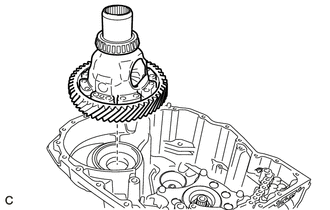
51. REMOVE DIFFERENTIAL CASE ASSEMBLY
| (a) Remove the differential case assembly from the automatic transaxle case sub-assembly. |
|
52. REMOVE DIFFERENTIAL CASE TAPERED ROLLER BEARING (REAR SIDE OUTER RACE)
| (a) Using SST, remove the differential case tapered roller bearing (rear side outer race) and shim from the automatic transaxle case sub-assembly. SST: 09308-00010 |
|
.png)
53. REMOVE FRONT DRIVE SHAFT OIL SEAL LH
| (a) Using SST and a hammer, remove the front drive shaft oil seal LH from the automatic transaxle case sub-assembly. SST: 09950-60010 09951-00650 SST: 09950-70010 09951-07200 |
|
.png)
54. REMOVE COUNTER DRIVEN GEAR TAPERED ROLLER BEARING (REAR SIDE OUTER RACE)
| (a) Using SST, remove the counter driven gear tapered roller bearing (rear side outer race) and shim from the automatic transaxle case sub-assembly. SST: 09308-00010 |
|
.png)
55. REMOVE TRANSMISSION LUBE APPLY TUBE
| (a) Remove the bolt and clamp from the automatic transaxle case sub-assembly. |
|
.png)
| (b) Remove the transmission lube apply tube from the automatic transaxle case sub-assembly. |
|
.png)
56. REMOVE B-1 BRAKE PISTON
| (a) Using snap ring pliers, remove the snap ring from the automatic transaxle case sub-assembly. |
|
.png)
(b) Set the automatic transaxle case sub-assembly so that the B-1 brake piston is positioned downward.
| (c) Apply compressed air (approximately 392 kPa (4.0 kgf/cm2, 57 psi)) to the ATF hole. NOTICE:
|
|
.png)
| (d) Remove the brake piston cover, B-1 brake piston and B-1 brake piston compression spring from the automatic transaxle case sub-assembly. |
|
.png)
| (e) Remove the 3 O-rings from the brake piston cover. |
|
.png)
| (f) Remove the O-ring from the B-1 brake piston. |
|
.png)
57. REMOVE FRONT PLANETARY GEAR SUB-ASSEMBLY
| (a) Disengage the wire harness clamp. |
|
.png)
(b) Remove the bolt and clamp from the automatic transaxle case sub-assembly.
| (c) Using a T55 "TORX" socket wrench, remove the 6 bolts. |
|
.png)
| (d) Remove the front planetary gear sub-assembly from the automatic transaxle case sub-assembly. |
|
.png)
| (e) Remove the bolt, transmission revolution sensor (NC) and spacer from the front planetary gear sub-assembly. |
|
.png)
58. REMOVE PLANETARY SUN GEAR SUB-ASSEMBLY
| (a) Remove the planetary sun gear sub-assembly from the rear planetary gear assembly. |
|
.png)
| (b) Remove the thrust needle roller bearing from the rear planetary gear assembly. |
|
.png)
59. REMOVE REAR PLANETARY GEAR ASSEMBLY
| (a) Remove the No. 3 planetary carrier thrust washer from the rear planetary gear assembly. |
|
.png)
| (b) Using a screwdriver with its tip wrapped with protective tape, remove the snap ring from the automatic transaxle case sub-assembly. NOTICE: Be careful not to damage the automatic transaxle case sub-assembly. |
|
.png)
| (c) Remove the one-way clutch assembly with rear planetary gear assembly from the C-2 clutch assembly. |
|
.png)
| (d) Remove the one-way clutch assembly from the rear planetary gear assembly. |
|
.png)
| (e) Remove the No. 4 planetary carrier thrust washer from the rear planetary gear assembly. |
|
.png)
60. INSPECT ONE-WAY CLUTCH ASSEMBLY
Click here
61. INSPECT REAR PLANETARY GEAR ASSEMBLY
Click here
62. REMOVE REAR PLANETARY SUN GEAR SUB-ASSEMBLY
| (a) Remove the rear planetary sun gear sub-assembly from the C-2 clutch assembly. |
|
.png)
(b) Remove the No. 4 thrust bearing race and No. 3 thrust bearing race from the rear planetary sun gear sub-assembly.
63. INSPECT REAR PLANETARY SUN GEAR SUB-ASSEMBLY
Click here
64. INSPECT CLEARANCE OF NO. 2 BRAKE
Click here
65. INSPECT CLEARANCE OF C-2 CLUTCH
Click here
66. REMOVE 1ST AND REVERSE BRAKE CLUTCH DISC
| (a) Using a screwdriver with its tip wrapped with protective tape, remove the snap ring from the automatic transaxle case sub-assembly. NOTICE: Be careful not to damage the automatic transaxle case sub-assembly. |
|
.png)
| (b) Remove the 2 1st and reverse brake flanges, 5 1st and reverse brake clutch discs and 4 1st and reverse brake clutch plates from the automatic transaxle case sub-assembly. |
|
.png)
67. INSPECT 1ST AND REVERSE BRAKE CLUTCH DISC
Click here
68. REMOVE C-2 CLUTCH ASSEMBLY
| (a) Remove the thrust needle roller bearing and No. 2 thrust bearing race from the C-2 clutch assembly. |
|
.png)
| (b) Remove the C-2 clutch assembly from the automatic transaxle case sub-assembly. |
|
.png)
(c) Remove the thrust needle roller bearing from the C-2 clutch assembly.
69. REMOVE NO. 2 CLUTCH DISC
| (a) Using a screwdriver with its tip wrapped with protective tape, remove the snap ring from the intermediate shaft sub-assembly. NOTICE: Be careful not to damage the intermediate shaft sub-assembly. |
|
.png)
| (b) Remove the direct clutch flange, 4 No. 2 clutch discs and 4 No. 2 clutch plates from the intermediate shaft sub-assembly. |
|
.png)
70. INSPECT NO. 2 CLUTCH DISC
Click here
71. REMOVE C-2 CLUTCH BALANCER
| (a) Place SST on the C-2 clutch balancer and compress the clutch return with retainer spring sub-assembly with a press. SST: 09387-00020 |
|
.png)
(b) Using a snap ring expander, remove the snap ring from the intermediate shaft sub-assembly.
NOTICE:
Do not expand the snap ring excessively.
| (c) Apply compressed air (approximately 392 kPa (4.0 kgf/cm2, 57 psi)) to the ATF hole. |
|
.png)
| (d) Remove the C-2 clutch balancer from the intermediate shaft sub-assembly. |
|
.png)
72. REMOVE CLUTCH RETURN WITH RETAINER SPRING SUB-ASSEMBLY
| (a) Remove the clutch return with retainer spring sub-assembly from the intermediate shaft sub-assembly. |
|
.png)
73. INSPECT CLUTCH RETURN WITH RETAINER SPRING SUB-ASSEMBLY
Click here
74. REMOVE C-2 CLUTCH PISTON
| (a) Cover the ATF holes shown in the illustration and apply compressed air (approximately 392 kPa (4.0 kgf/cm2, 57 psi)) to the ATF hole. |
|
.png)
| (b) Remove the C-2 clutch piston from the intermediate shaft sub-assembly. |
|
.png)
75. REMOVE INTERMEDIATE SHAFT O-RING
| (a) Remove the 2 intermediate shaft O-rings from the intermediate shaft sub-assembly. |
|
.png)
76. REMOVE 1ST AND REVERSE BRAKE PISTON
| (a) Place SST on the 1st and reverse brake return spring sub-assembly and compress it with a press. SST: 09387-00140 SST: 09950-60010 09951-00650 SST: 09950-70010 09951-07200 NOTICE:
|
|
.png)
(b) Using a screwdriver with its tip wrapped with protective tape, remove the snap ring from the automatic transaxle case sub-assembly.
NOTICE:
Be careful not to damage the automatic transaxle case sub-assembly.
| (c) Remove the 1st and reverse brake return spring sub-assembly from the 1st and reverse brake piston. |
|
.png)
| (d) Apply compressed air (approximately 392 kPa (4.0 kgf/cm2, 57 psi)) to the ATF hole to remove the 1st and reverse brake piston from the automatic transaxle case sub-assembly. |
|
.png)
| (e) Remove the 2 O-rings from the 1st and reverse brake piston. |
|
.png)
77. INSPECT 1ST AND REVERSE BRAKE RETURN SPRING SUB-ASSEMBLY
Click here
78. REMOVE NO. 1 THRUST BEARING RACE
| (a) Remove the No. 1 thrust bearing race from the automatic transaxle case sub-assembly. |
|
.png)
79. REMOVE DIRECT CLUTCH DRUM OIL SEAL RING
| (a) Remove the 2 direct clutch drum oil seal rings from the automatic transaxle case sub-assembly. |
|
.png)
80. REMOVE BREATHER PLUG
| (a) Disengage each claw and remove the breather plug from the automatic transaxle case sub-assembly. |
|
.png)
| (b) Using a screwdriver with its tip wrapped with protective tape, remove the O-ring from the breather plug. NOTICE: Be careful not to damage the breather plug. |
|
.png)
81. REMOVE MANUAL VALVE LEVER SHAFT OIL SEAL
| (a) Using a screwdriver with its tip wrapped with protective tape, remove the manual valve lever shaft oil seal from the automatic transaxle case sub-assembly. NOTICE: Be careful not to damage the automatic transaxle case sub-assembly. |
|
.png)
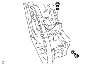
82. REMOVE NO. 1 TRANSAXLE CASE PLUG
| (a) Remove the 4 No. 1 transaxle case plugs from the automatic transaxle case sub-assembly. |
|
.png)
(b) Remove the 4 O-rings from the 4 No. 1 transaxle case plugs.
| (c) Remove the 3 No. 1 transaxle case plugs from the transaxle housing. |
|
.png)
(d) Remove the 3 O-rings from the 3 No. 1 transaxle case plugs.
83. REMOVE NO. 2 TRANSAXLE CASE PLUG
| (a) Using a T55 "TORX" socket wrench, remove the 2 No. 2 transaxle case plugs from the transaxle housing. |
|
(b) Remove the 2 O-rings from the 2 No. 2 transaxle case plugs.
| (c) Using a T55 "TORX" socket wrench, remove the 2 No. 2 transaxle case plugs from the automatic transaxle case sub-assembly. |
|
.png)
(d) Remove the 2 O-rings from the 2 No. 2 transaxle case plugs.
 Inspection
INSPECTION PROCEDURE 1. INSPECT TRANSMISSION OIL CLEANER MAGNET (a) Use the removed transmission oil cleaner magnets to collect any steel chips. Examine the chips and particles in the transaxle hou ...
 Reassembly
REASSEMBLY CAUTION / NOTICE / HINT HINT: Check each bearing position and installation direction. Mark Front Thrust Bearing Race Diameter Inside / Outside (mm (in.)) Thrust Bearing Diameter In ...
Other materials:
Lexus RX (RX 350L, RX450h) 2016-2026 Repair Manual > Lighting System (w/ Automatic Headlight Beam Level Control System): Variation Code not Written (B2451)
DESCRIPTION The No. 1 headlight ECU sub-assembly LH stores this DTC if the vehicle specifications have not been stored. DTC No. Detection Item DTC Detection Condition Trouble Area DTC Output from B2451 Variation Code not Written
The engine switch is on (IG).
Vehicle speci ...
Lexus RX (RX 350L, RX450h) 2016-2026 Repair Manual > Rear Seat Side Airbag Assembly (for Captain Seat Type): Removal
REMOVAL CAUTION / NOTICE / HINT The necessary procedures (adjustment, calibration, initialization, or registration) that must be performed after parts are removed, installed, or replaced during the rear seat airbag assembly removal/installation are shown below. Necessary Procedure After Parts Remove ...
Lexus RX (RX 350L, RX450h) 2016-{YEAR} Owners Manual
- For your information
- Pictorial index
- For safety and security
- Instrument cluster
- Operation of each component
- Driving
- Lexus Display Audio system
- Interior features
- Maintenance and care
- When trouble arises
- Vehicle specifications
- For owners
Lexus RX (RX 350L, RX450h) 2016-{YEAR} Repair Manual

0.0144