
Lexus RX (RX 350L, RX450h) 2016-2026 Repair Manual: Removal
REMOVAL
CAUTION / NOTICE / HINT
The necessary procedures (adjustment, calibration, initialization, or registration) that must be performed after parts are removed and installed, or replaced during rear bumper assembly removal/installation are shown below.
Necessary Procedures After Parts Removed/Installed/Replaced| Replaced Part or Performed Procedures | Necessary Procedures | Effect/Inoperative Function When Necessary Procedures are not Performed | Link |
|---|---|---|---|
|
*1: When performing learning using the Techstream.
Click here | |||
| w/ Kick Sensor
| Memorize steering angle neutral point | Lane Control System | |
| Pre-collision System | |||
| Intelligent Clearance Sonar System*1 | |||
| Parking Assist Monitor System | | ||
| Panoramic View Monitor System | | ||
| Lighting System (w/ Automatic Headlight Beam Level Control System) | | ||
| Initialize back door lock | Power Door Lock Control System | | |
| Reset back door close position | Power Back Door System (w/ Outside Door Control Switch) | | |
| w/ Intelligent Clearance Sonar System
|
|
| |
PROCEDURE
1. PRECAUTION (w/ Kick Sensor)
NOTICE:
After turning the engine switch off, waiting time may be required before disconnecting the cable from the negative (-) battery terminal. Therefore, make sure to read the disconnecting the cable from the negative (-) battery terminal notices before proceeding with work.
Click here .gif)
2. DISCONNECT CABLE FROM NEGATIVE BATTERY TERMINAL (w/ Kick Sensor)
NOTICE:
When disconnecting the cable, some systems need to be initialized after the cable is reconnected.
Click here
3. REMOVE REAR LIGHT COVER LH
for Bulb Type Turn Signal Light:
Click here
for LED Type Turn Signal Light:
Click here
4. REMOVE REAR LIGHT COVER RH
HINT:
Use the same procedure as for the LH side.
5. DISCONNECT QUARTER OUTSIDE MOULDING SUB-ASSEMBLY LH
(a) Apply protective tape around the quarter outside moulding sub-assembly LH and rear bumper assembly as shown in the illustration.
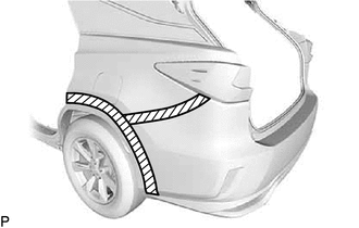
.png) | Protective Tape |
| (b) Using a 4 mm hexagon socket wrench, remove the screw. |
|
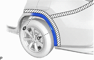
(c) Remove the clip.
(d) Pull back the edge of the rear wheel house liner LH and disengage the 4 claws by pushing the area indicated by the arrow in the illustration with a finger.
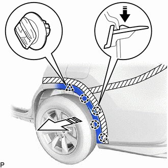
.png) | Remove in this Direction (1) |
.png) | Remove in this Direction (2) |
NOTICE:
- Do not apply excessive force when pulling back the rear wheel house liner LH.
- To avoid damaging the claws, do not forcibly pull the quarter outside moulding sub-assembly LH.
(e) Disengage the clip to disconnect the quarter outside moulding sub-assembly LH from the rear bumper assembly.
6. DISCONNECT QUARTER OUTSIDE MOULDING SUB-ASSEMBLY RH
HINT:
Use the same procedure as for the LH side.
7. REMOVE LUGGAGE COMPARTMENT SIDE COVER LH (w/o Spare Tire)
(a) Remove the 6 clips.
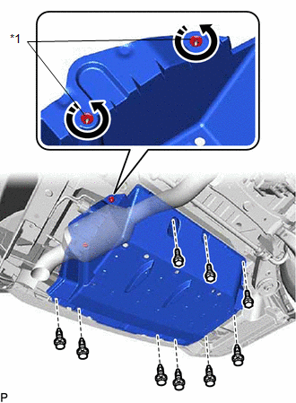
| *1 | Luggage Compartment Side Cover Protector Clip |
| | Remove in this Direction |
(b) Disengage the 2 luggage compartment side cover protector clips as shown in the illustration.
(c) Remove the 3 bolts and luggage compartment side cover LH.
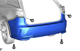
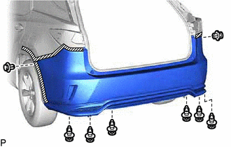
8. REMOVE REAR BUMPER ASSEMBLY
| (a) Remove the 4 screws. |
|
| (b) Remove the 8 clips. |
|
(c) Disengage the 6 claws as shown in the illustration.
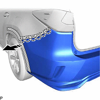
| | Remove in this Direction |
HINT:
Use the same procedure for the RH side and LH side.
(d) Disengage the 2 claws as shown in the illustration to remove the rear bumper assembly.
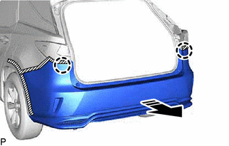
| | Remove in this Direction |
(e) w/ Intuitive Parking Assist System or Kick Sensor:
(1) Disconnect the connector.
 Components
COMPONENTS ILLUSTRATION *A w/o Spare Tire - - *1 LUGGAGE COMPARTMENT SIDE COVER LH *2 QUARTER OUTSIDE MOULDING SUB-ASSEMBLY LH *3 QUARTER OUTSIDE MOULDING SUB-ASSEMBLY RH * ...
 Installation
INSTALLATION PROCEDURE 1. INSTALL REAR BUMPER ASSEMBLY (a) w/ Intuitive Parking Assist System or Kick Sensor: (1) Connect the connector. (b) Engage the 2 claws as shown in the illustration. Ins ...
Other materials:
Lexus RX (RX 350L, RX450h) 2016-2026 Repair Manual > Rear Seat Inner Belt Assembly(for Rh Side): Installation
INSTALLATION PROCEDURE 1. INSTALL REAR SEAT 3 POINT TYPE BELT ASSEMBLY RH (a) Install the rear seat 3 point type belt assembly RH with the bolt. Torque: 42 N·m {428 kgf·cm, 31 ft·lbf} (b) Connect the connector. (c) Engage each clamp. 2. INSTALL SEPARATE TYPE REAR SEAT CUSHION COVER WITH PAD Clic ...
Lexus RX (RX 350L, RX450h) 2016-2026 Owners Manual > Intelligent Clearance Sonar
(ICS): Rear Cross Traffic Auto Brake function (if equipped)
If the Rear Cross Traffic Auto Brake function detects that a collision with
an
approaching vehicle is possible, the hybrid system output will be restricted to
restrain any increase in vehicle speed. (Hybrid system output restriction
control:
See A below.)
Additionally, if the accelerator ped ...
Lexus RX (RX 350L, RX450h) 2016-{YEAR} Owners Manual
- For your information
- Pictorial index
- For safety and security
- Instrument cluster
- Operation of each component
- Driving
- Lexus Display Audio system
- Interior features
- Maintenance and care
- When trouble arises
- Vehicle specifications
- For owners
Lexus RX (RX 350L, RX450h) 2016-{YEAR} Repair Manual

0.0112