Lexus RX (RX 350L, RX450h) 2016-2026 Repair Manual: Removal
REMOVAL
CAUTION / NOTICE / HINT
The necessary procedures (adjustment, calibration, initialization or registration) that must be performed after parts are removed and installed, or replaced during front engine mounting insulator removal/installation are shown below.
Necessary Procedures After Parts Removed/Installed/Replaced| Replaced Part or Performed Procedure | Necessary Procedure | Effect/Inoperative Function when Necessary Procedure not Performed | Link |
|---|---|---|---|
| Battery terminal is disconnected/reconnected | Memorize steering angle neutral point | Lane Control System | |
| Pre-collision System | |||
| Intelligent Clearance Sonar System*1 | |||
| Parking Assist Monitor System | | ||
| Panoramic View Monitor System | | ||
| Lighting System (w/ Automatic Headlight Beam Level Control System) | | ||
| Initialize back door lock | Power Door Lock Control System | | |
| Reset back door close position | Power Back Door System (w/ Outside Door Control Switch) | | |
| Replacement of ECM | Vehicle Identification Number (VIN) registration | MIL comes on | |
| ECU communication ID registration (Immobiliser system) | Engine start function | | |
| Perform the following procedures in the order shown (If possible, read the transaxle compensation code from the previous ECM):
|
| | |
| Perform the following procedures in the order shown (If impossible, read the transaxle compensation code from the previous ECM):
| |||
| Perform code registration (Immobiliser system) |
| | |
| Inspection after repair |
| |
| Front wheel alignment adjustment | Calibration |
| |
| Suspension, tires, etc. (The vehicle height changes because of suspension or tire replacement) |
|
| |
| Rear television camera assembly optical axis (Back camera position setting) | Parking assist monitor system | | |
| Panoramic view monitor system | | |
| Initialize No. 1 headlight ECU sub-assembly LH | Lighting System (w/ Automatic Headlight Beam Level Control System) | |
*1: When performing learning using the Techstream.
Click here .gif)
PROCEDURE
1. REMOVE FRONT FRAME ASSEMBLY
Click here
2. REMOVE FRONT ENGINE MOUNTING INSULATOR
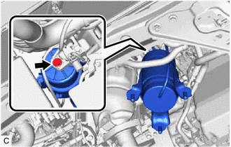
| (a) Disconnect the vacuum hose from the No. 2 vacuum switching valve assembly. |
|
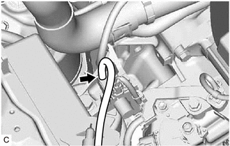
| (b) Remove the bolt and front engine mounting insulator from the front engine mounting bracket. |
|
 On-vehicle Inspection
ON-VEHICLE INSPECTION PROCEDURE 1. INSPECT FRONT ENGINE MOUNTING INSULATOR (a) Disconnect the vacuum hose from the front engine mounting insulator assembly. (b) Using a vacuum pump, apply vacuum of ...
 Installation
INSTALLATION PROCEDURE 1. INSTALL FRONT ENGINE MOUNTING INSULATOR (a) Install the front engine mounting insulator to the front engine mounting bracket with the bolt. Torque: 87 N·m {887 kgf·cm, 64 ...
Other materials:
Lexus RX (RX 350L, RX450h) 2016-2026 Repair Manual > Headlight Cleaner Actuator: Components
COMPONENTS ILLUSTRATION *1 FRONT BUMPER ASSEMBLY *2 HEADLIGHT WASHER ACTUATOR SUB-ASSEMBLY LH *3 HEADLIGHT WASHER ACTUATOR SUB-ASSEMBLY RH *4 HEADLIGHT WASHER COVER LH *5 HEADLIGHT WASHER COVER RH - - ...
Lexus RX (RX 350L, RX450h) 2016-2026 Repair Manual > Headlight Assembly: Adjustment
ADJUSTMENT CAUTION / NOTICE / HINT HINT:
Use the same procedure for the RH side and LH side.
The following procedure is for the LH side.
PROCEDURE 1. PREPARE VEHICLE FOR HEADLIGHT AIM ADJUSTMENT (a) Prepare the vehicle:
Ensure that there is no damage or deformation to the vehicle body aro ...
Lexus RX (RX 350L, RX450h) 2016-{YEAR} Owners Manual
- For your information
- Pictorial index
- For safety and security
- Instrument cluster
- Operation of each component
- Driving
- Lexus Display Audio system
- Interior features
- Maintenance and care
- When trouble arises
- Vehicle specifications
- For owners
Lexus RX (RX 350L, RX450h) 2016-{YEAR} Repair Manual

0.0112