Lexus RX (RX 350L, RX450h) 2016-2026 Repair Manual: Crankshaft Position Sensor
Components
COMPONENTS
ILLUSTRATION
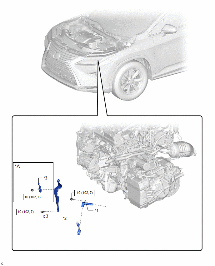
| *A | w/ Oil Cooler | - | - |
| *1 | CRANKSHAFT POSITION SENSOR | *2 | CRANKSHAFT POSITION SENSOR PROTECTOR |
| *3 | HOSE CLAMP | - | - |
.png) | N*m (kgf*cm, ft.*lbf): Specified torque | - | - |
Removal
REMOVAL
CAUTION / NOTICE / HINT
The necessary procedures (adjustment, calibration, initialization or registration) that must be performed after parts are removed and installed, or replaced during crankshaft position sensor removal/installation are shown below.
Necessary Procedures After Parts Removed/Installed/Replaced| Replaced Part or Performed Procedure | Necessary Procedure | Effect/Inoperative Function when Necessary Procedure not Performed | Link |
|---|---|---|---|
| Inspection After Repair |
| |
CAUTION:
-
To prevent burns, do not touch the engine, exhaust manifold or other high temperature components while the engine is hot.
.png)
-
To prevent burns, do not touch the engine, exhaust pipe or other high temperature components while the engine is hot.
.png)
PROCEDURE
1. REMOVE EXHAUST MANIFOLD SUB-ASSEMBLY LH (TWC: Front Catalyst)
Click here .gif)
2. REMOVE CRANKSHAFT POSITION SENSOR PROTECTOR
(a) w/ oil cooler:
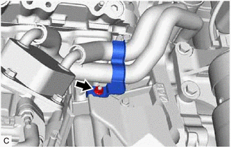
| (1) Remove the nut and hose clamp from the crankshaft position sensor protector. |
|
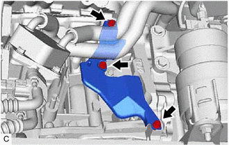
| (b) Remove the 3 bolts and crankshaft position sensor protector from the cylinder block sub-assembly and oil pan sub-assembly. |
|
3. REMOVE CRANKSHAFT POSITION SENSOR
| (a) Disconnect the crankshaft position sensor connector. |
|
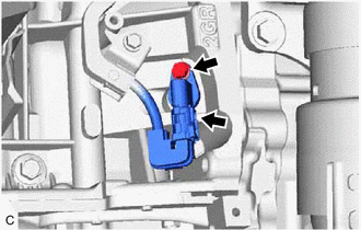
(b) Remove the bolt and crankshaft position sensor from the cylinder block sub-assembly.
NOTICE:
If the crankshaft position sensor has been struck or dropped, replace it.
Installation
INSTALLATION
PROCEDURE
1. INSTALL CRANKSHAFT POSITION SENSOR
(a) Apply a light coat of engine oil to the O-ring of the crankshaft position sensor.
NOTICE:
If reusing the crankshaft position sensor, be sure to inspect the O-ring.
(b) Install the crankshaft position sensor to the cylinder block sub-assembly with the bolt.
Torque:
10 N·m {102 kgf·cm, 7 ft·lbf}
NOTICE:
- If the crankshaft position sensor has been struck or dropped, replace it.
- Make sure that the O-ring is not cracked or moved out of place when installing the crankshaft position sensor.
(c) Connect the crankshaft position sensor connector.
2. INSTALL CRANKSHAFT POSITION SENSOR PROTECTOR
(a) Install the crankshaft position sensor protector to the cylinder block sub-assembly and oil pan sub-assembly with the 3 bolts.
Torque:
10 N·m {102 kgf·cm, 7 ft·lbf}
(b) w/ oil cooler:
(1) Install the hose clamp to the crankshaft position sensor prtected with the nut.
Torque:
10 N·m {102 kgf·cm, 7 ft·lbf}
3. INSTALL EXHAUST MANIFOLD SUB-ASSEMBLY LH (TWC: Front Catalyst)
Click here .gif)
 Installation
INSTALLATION PROCEDURE 1. INSTALL VVT SENSOR (for Exhaust Side of Bank 2) (a) Apply a light coat of engine oil to the O-ring of the VVT sensor. NOTICE: If reusing the VVT sensor, be sure to inspect th ...
 Ecm
Ecm
...
Other materials:
Lexus RX (RX 350L, RX450h) 2016-2026 Repair Manual > Steering Lock System: System Diagram
SYSTEM DIAGRAM Circuit Description Component Outline Steering Lock ECU (Steering Lock Actuator or Upper Bracket Assembly)
The steering is locked and unlocked by communicating with the certification ECU (smart key ECU assembly) and ID code box (immobiliser code ECU) via LIN communicati ...
Lexus RX (RX 350L, RX450h) 2016-2026 Repair Manual > Audio And Visual System (for 8 Inch Display): Display Malfunction (B15A6,B15B0)
DESCRIPTION These DTCs are stored when a malfunction occurs in the multi-display assembly. DTC No. Detection Item DTC Detection Condition Trouble Area B15A6 Display Malfunction When any of the following conditions is met:
RAM error
Drawing controller malfunction
Internal hard ...
Lexus RX (RX 350L, RX450h) 2016-{YEAR} Owners Manual
- For your information
- Pictorial index
- For safety and security
- Instrument cluster
- Operation of each component
- Driving
- Lexus Display Audio system
- Interior features
- Maintenance and care
- When trouble arises
- Vehicle specifications
- For owners
Lexus RX (RX 350L, RX450h) 2016-{YEAR} Repair Manual

0.0107