Lexus RX (RX 350L, RX450h) 2016-2026 Repair Manual: Installation
INSTALLATION
CAUTION / NOTICE / HINT
HINT:
- Use the same procedure for the RH side and LH side.
- The following procedure is for the LH side.
- If the front speed sensor rotor needs to be replaced, replace the front axle hub sub-assembly.
PROCEDURE
1. INSTALL FRONT SPEED SENSOR (w/o AVS)
(a) Install the front speed sensor to the steering knuckle with the bolt.
Torque:
8.5 N·m {87 kgf·cm, 75 in·lbf}
NOTICE:
- Keep the tip of the front speed sensor and installation hole free of foreign matter.
- Firmly insert the front speed sensor body into the steering knuckle before tightening the bolt.
- After installing the front speed sensor to the steering knuckle, make sure that there is no clearance between the front speed sensor stay and steering knuckle. Also make sure that no foreign matter is stuck between the parts.
- Do not twist the front speed sensor wire harness when installing it.
(b) Engage the 2 claws to install the sensor clamp.
NOTICE:
Do not twist the front speed sensor wire harness when installing it.
| (c) Engage the 2 claws to install the sensor clamp. NOTICE: Do not twist the front speed sensor wire harness when installing it. |
|
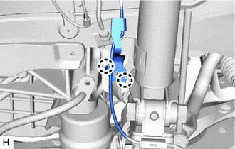
| (d) Install the front flexible hose with the bolt. Torque: 18.8 N·m {192 kgf·cm, 14 ft·lbf} |
|
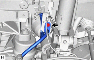
(e) Install the sensor clamp with the bolt.
Torque:
8.5 N·m {87 kgf·cm, 75 in·lbf}
NOTICE:
Do not twist the front speed sensor wire harness when installing it.
(f) Engage the 2 sensor clamps.
NOTICE:
Do not twist the front speed sensor wire harness when installing it.
(g) Connect the front speed sensor connector.
(h) Return the front fender splash shield sub-assembly to its original position.
2. INSTALL FRONT SKID CONTROL SENSOR WIRE (w/ AVS)
(a) Install the front skid control sensor wire to the front shock absorber assembly with the bolt.
Torque:
10 N·m {102 kgf·cm, 7 ft·lbf}
(b) Connect the connector to the front shock absorber assembly.
NOTICE:
Do not twist the front skid control sensor wire harness when installing it.
| (c) Engage the 2 claws to install the sensor clamp. NOTICE: Do not twist the front skid control sensor wire harness when installing it. |
|
| (d) Install the front flexible hose with the bolt. Torque: 18.8 N·m {192 kgf·cm, 14 ft·lbf} |
|
(e) Install the sensor clamp with the bolt.
Torque:
8.5 N·m {87 kgf·cm, 75 in·lbf}
NOTICE:
Do not twist the front skid control sensor wire harness when installing it.
(f) Engage the 2 sensor clamps.
NOTICE:
Do not twist the front skid control sensor wire harness when installing it.
(g) Connect the front skid control sensor wire connector.
(h) Return the front fender splash shield sub-assembly to its original position.
3. INSTALL FRONT SPEED SENSOR (w/ AVS)
(a) Install the front speed sensor to the steering knuckle with the bolt.
Torque:
8.5 N·m {87 kgf·cm, 75 in·lbf}
NOTICE:
- Keep the tip of the front speed sensor and installation hole free of foreign matter.
- Firmly insert the front speed sensor body into the steering knuckle before tightening the bolt.
- After installing the front speed sensor to the steering knuckle, make sure that there is no clearance between the front speed sensor stay and steering knuckle. Also make sure that no foreign matter is stuck between the parts.
- Do not twist the front speed sensor wire harness when installing it.
(b) Connect the front speed sensor connector.
4. INSTALL FRONT FENDER SPLASH SHIELD SUB-ASSEMBLY
(a) Install the front fender splash shield sub-assembly with the screw and clip.
5. INSTALL FRONT WHEEL
Click here .gif)
6. CHECK FOR SPEED SENSOR SIGNAL
Click here
 Components
COMPONENTS ILLUSTRATION *A w/o AVS - - *1 FRONT FENDER SPLASH SHIELD SUB-ASSEMBLY *2 FRONT SPEED SENSOR *3 FRONT FLEXIBLE HOSE - - N*m (kgf*cm, ft.*lbf): Specified ...
 Removal
REMOVAL CAUTION / NOTICE / HINT HINT:
Use the same procedure for the RH side and LH side.
The following procedure is for the LH side.
If the front speed sensor rotor needs to be replaced, repla ...
Other materials:
Lexus RX (RX 350L, RX450h) 2016-2026 Repair Manual > Rear Differential Carrier Assembly: Disassembly
DISASSEMBLY CAUTION / NOTICE / HINT NOTICE:
Before installation, thoroughly clean and dry each part and then apply Toyota Genuine Differential gear oil LT SAE 75W-85 GL-5 or equivalent to them.
Do not use alkaline cleaner for aluminum or rubber parts and rear differential case bolts.
Do not c ...
Lexus RX (RX 350L, RX450h) 2016-2026 Repair Manual > Intuitive Parking Assist System (w/ Intelligent Clearance Sonar System): Customize Parameters
CUSTOMIZE PARAMETERS CUSTOMIZE INTUITIVE PARKING ASSIST SYSTEM (a) Customizing with the Techstream. NOTICE:
When the customer requests a change in a function, first make sure that the function can be customized.
Be sure to make a note of the current settings before customizing.
When troublesh ...
Lexus RX (RX 350L, RX450h) 2016-{YEAR} Owners Manual
- For your information
- Pictorial index
- For safety and security
- Instrument cluster
- Operation of each component
- Driving
- Lexus Display Audio system
- Interior features
- Maintenance and care
- When trouble arises
- Vehicle specifications
- For owners
Lexus RX (RX 350L, RX450h) 2016-{YEAR} Repair Manual

0.013