Lexus RX (RX 350L, RX450h) 2016-2026 Repair Manual: Removal
REMOVAL
CAUTION / NOTICE / HINT
The necessary procedures (adjustment, calibration, initialization or registration) that must be performed after parts are removed and installed, or replaced during ECM removal/installation are shown below.
Necessary Procedure After Parts Removed/Installed/Replaced| Replaced Part or Performed Procedure | Necessary Procedure | Effect/Inoperative Function when Necessary Procedure not Performed | Link |
|---|---|---|---|
| Battery terminal is disconnected/reconnected | Memorize steering angle neutral point | Lane Control System | |
| Pre-collision System | |||
| Intelligent Clearance Sonar System*1 | |||
| Parking Assist Monitor System | | ||
| Panoramic View Monitor System | | ||
| Lighting System (w/ Automatic Headlight Beam Level Control System) | | ||
| Initialize back door lock | Power Door Lock Control System | | |
| Reset back door close position | Power Back Door System (w/ Outside Door Control Switch) | | |
| Replacement of ECM | Vehicle Identification Number (VIN) registration | MIL comes on | |
| ECU communication ID registration (Immobiliser system) | Engine start function | | |
| Perform the following procedures in the order shown (If possible, read the transaxle compensation code from the previous ECM):
|
| | |
| Perform the following procedures in the order shown (If impossible, read the transaxle compensation code from the previous ECM):
| |||
| Perform code registration (Immobiliser system) |
| |
*1: When performing learning using the Techstream.
Click here .gif)
PROCEDURE
1. PRECAUTION
NOTICE:
-
Perform Vehicle Identification Number (VIN) registration when replacing the ECM.
Click here
-
Before replacing the ECM, refer to Registration.
Click here
- If the ECM has been struck or dropped, replace it.
-
After turning the engine switch off, waiting time may be required before disconnecting the cable from the negative (-) battery terminal. Therefore, make sure to read the disconnecting the cable from the negative (-) battery terminal notices before proceeding with work.
Click here
2. DISCONNECT CABLE FROM NEGATIVE BATTERY TERMINAL
NOTICE:
When disconnecting the cable, some systems need to be initialized after the cable is reconnected.
Click here
3. REMOVE COOL AIR INTAKE DUCT SEAL
Click here
4. REMOVE ECM
| (a) Raise the 2 levers while pushing the locks on the levers, and disconnect the 2 ECM connectors. NOTICE: After disconnecting the ECM connectors, make sure that dirt, water or other foreign matter does not contact the connecting parts of the ECM connectors. |
|
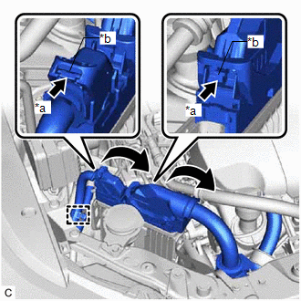
(b) Disengage the wire harness clamp.
(c) Remove the 2 bolts and nut to remove the ECM.
NOTICE:
If the ECM has been struck or dropped, replace it.
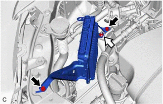
.png) | Bolt |
.png) | Nut |
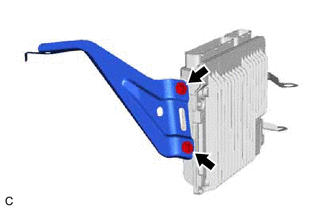
5. REMOVE NO. 1 ECM BRACKET
| (a) Remove the 2 bolts and No. 1 ECM bracket from the ECM. |
|
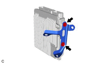
6. REMOVE NO. 2 ECM BRACKET
| (a) Remove the 2 bolts and No. 2 ECM bracket from the ECM. |
|
 Components
COMPONENTS ILLUSTRATION *1 ECM *2 NO. 1 ECM BRACKET *3 NO. 2 ECM BRACKET *4 COOL AIR INTAKE DUCT SEAL N*m (kgf*cm, ft.*lbf): Specified torque - - ...
 Installation
INSTALLATION PROCEDURE 1. INSTALL NO. 2 ECM BRACKET (a) Install the No. 2 ECM bracket to the ECM with the 2 bolts. Torque: 3.0 N·m {31 kgf·cm, 27 in·lbf} 2. INSTALL NO. 1 ECM BRACKET (a) Install t ...
Other materials:
Lexus RX (RX 350L, RX450h) 2016-2026 Repair Manual > Rear Center Seat Inner Belt Assembly(w/ Rear No. 2 Seat): Installation
INSTALLATION PROCEDURE 1. INSTALL REAR CENTER SEAT INNER BELT ASSEMBLY (a) Install the rear center seat inner belt assembly with the bolt. Torque: 42 N·m {428 kgf·cm, 31 ft·lbf} NOTICE: Do not allow the anchor part of the rear center seat inner belt assembly to overlap the protruding parts of th ...
Lexus RX (RX 350L, RX450h) 2016-2026 Repair Manual > Sfi System: Ignition Circuit
DESCRIPTION A direct ignition system is used on this vehicle. The direct ignition system is a 1 cylinder ignition system which ignites one cylinder with one ignition coil. In the 1 cylinder ignition system, one spark plug is connected to the end of the secondary winding. High voltage is generated in ...
Lexus RX (RX 350L, RX450h) 2016-{YEAR} Owners Manual
- For your information
- Pictorial index
- For safety and security
- Instrument cluster
- Operation of each component
- Driving
- Lexus Display Audio system
- Interior features
- Maintenance and care
- When trouble arises
- Vehicle specifications
- For owners
Lexus RX (RX 350L, RX450h) 2016-{YEAR} Repair Manual

0.0104