Lexus RX (RX 350L, RX450h) 2016-2026 Repair Manual: Parts Location
PARTS LOCATION
ILLUSTRATION
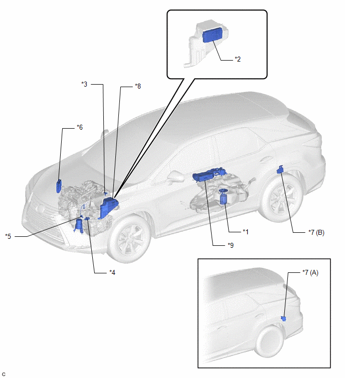
| *A | w/ Rear No. 2 Seat | *B | w/o Rear No. 2 Seat |
| *1 | FUEL PUMP (for Low Pressure Side) | *2 | SEMICONDUCTOR PWR INTEGRATION ECU |
| *3 | MASS AIR FLOW METER SUB-ASSEMBLY | *4 | PARK/NEUTRAL POSITION SWITCH ASSEMBLY |
| *5 | NO. 2 VACUUM SWITCHING VALVE ASSEMBLY (for Active Control Engine Mount) | *6 | ECM |
| *7 | FUEL PUMP CONTROL ECU ASSEMBLY | *8 | ENGINE ROOM RELAY BLOCK AND JUNCTION BLOCK ASSEMBLY |
| *9 | CANISTER | - | - |
ILLUSTRATION
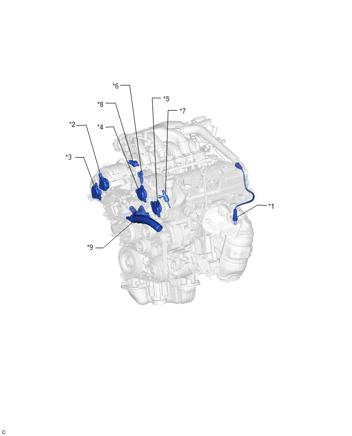
| *1 | AIR FUEL RATIO SENSOR (Bank 2 Sensor 1) | *2 | CAM TIMING OIL CONTROL SOLENOID ASSEMBLY (for Intake Camshaft of Bank 1) |
| *3 | CAM TIMING OIL CONTROL SOLENOID ASSEMBLY (for Exhaust Camshaft of Bank 1) | *4 | CAM TIMING OIL CONTROL SOLENOID ASSEMBLY (for Intake Camshaft of Bank 2) |
| *5 | CAM TIMING OIL CONTROL SOLENOID ASSEMBLY (for Exhaust Camshaft of Bank 2) | *6 | FUEL INJECTOR ASSEMBLY (for Port Injection) |
| *7 | FUEL INJECTOR ASSEMBLY (for Direct Injection) | *8 | FUEL PRESSURE SENSOR (for Low Pressure Side) |
| *9 | WATER INLET WITH THERMOSTAT SUB-ASSEMBLY | - | - |
ILLUSTRATION

| *1 | AIR FUEL RATIO SENSOR (Bank 1 Sensor 1) | *2 | ENGINE COOLANT TEMPERATURE SENSOR |
| *3 | FUEL PRESSURE SENSOR (for High Pressure Side) | *4 | FUEL PUMP ASSEMBLY (for High Pressure Side) |
| *5 | VVT SENSOR (for Intake Camshaft of Bank 1) | *6 | VVT SENSOR (for Exhaust Camshaft of Bank 1) |
| *7 | VVT SENSOR (for Intake Camshaft of Bank 2) | *8 | VVT SENSOR (for Exhaust Camshaft of Bank 2) |
| *9 | IGNITION COIL ASSEMBLY | *10 | CRANKSHAFT POSITION SENSOR |
ILLUSTRATION
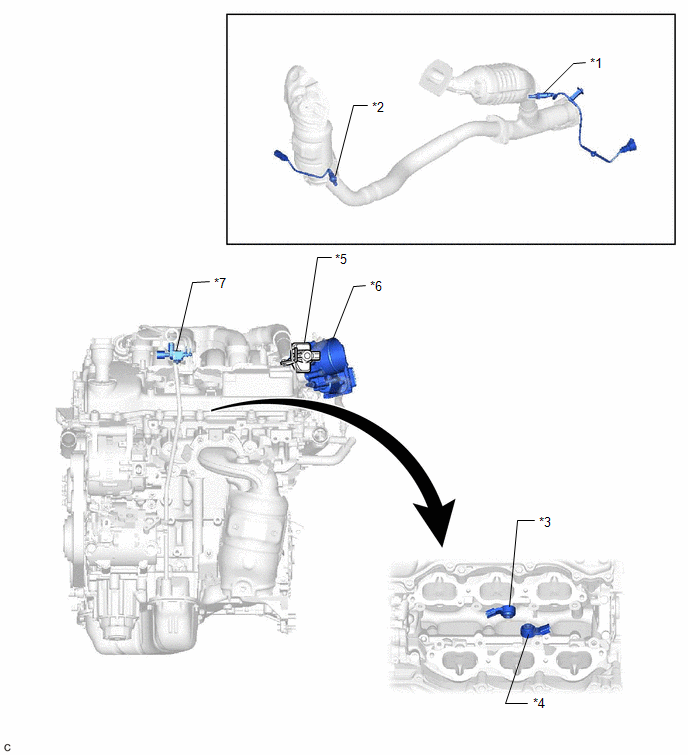
| *1 | HEATED OXYGEN SENSOR (Bank 1 Sensor 2) | *2 | HEATED OXYGEN SENSOR (Bank 2 Sensor 2) |
| *3 | KNOCK CONTROL SENSOR (Bank 1) | *4 | KNOCK CONTROL SENSOR (Bank 2) |
| *5 | PURGE VSV | *6 | THROTTLE BODY WITH MOTOR ASSEMBLY |
| *7 | NO. 1 VACUUM SWITCHING VALVE (for Intake Air Control Valve Sub-assembly) | - | - |
ILLUSTRATION
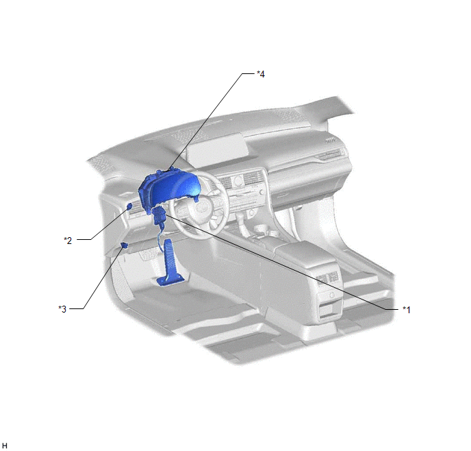
| *1 | ACCELERATOR PEDAL SENSOR ASSEMBLY | *2 | STOP LIGHT SWITCH ASSEMBLY |
| *3 | DLC3 | *4 | COMBINATION METER ASSEMBLY |
 Definition Of Terms
DEFINITION OF TERMS Term Definition Monitor Description Description of what the ECM monitors and how it detects malfunctions (monitoring purpose and details). Related DTCs Group of di ...
 System Diagram
SYSTEM DIAGRAM ...
Other materials:
Lexus RX (RX 350L, RX450h) 2016-2026 Repair Manual > Lumbar Support Adjuster Assembly: Components
COMPONENTS ILLUSTRATION *A for Standard Seat Type *B for Sports Seat Type *1 FRONT SEAT CUSHION SHIELD *2 FRONT SEAT INNER CUSHION SHIELD *3 INNER NO. 1 FRONT SEAT CUSHION SHIELD - - ILLUSTRATION *1 SEPARATE TYPE FRONT SEATBACK ASSEMBLY *2 SEPARATE TYPE FRO ...
Lexus RX (RX 350L, RX450h) 2016-2026 Repair Manual > Rear Seat Assembly (for 60/40 Split Seat Type Rh Side): Reassembly
REASSEMBLY CAUTION / NOTICE / HINT CAUTION: Wear protective gloves. Sharp areas on the seat frame may injure your hands. PROCEDURE 1. INSTALL REAR SEATBACK FRAME SUB-ASSEMBLY RH (a) Using a T40 "TORX" socket wrench, install the 4 bolts (B). Install in this Direction Torque: 29 N·m {296 k ...
Lexus RX (RX 350L, RX450h) 2016-{YEAR} Owners Manual
- For your information
- Pictorial index
- For safety and security
- Instrument cluster
- Operation of each component
- Driving
- Lexus Display Audio system
- Interior features
- Maintenance and care
- When trouble arises
- Vehicle specifications
- For owners
Lexus RX (RX 350L, RX450h) 2016-{YEAR} Repair Manual

0.0129