Lexus RX (RX 350L, RX450h) 2016-2026 Repair Manual: ABS Solenoid Control Module Actuator Stuck On (C143A7E,C143A7F)
DESCRIPTION
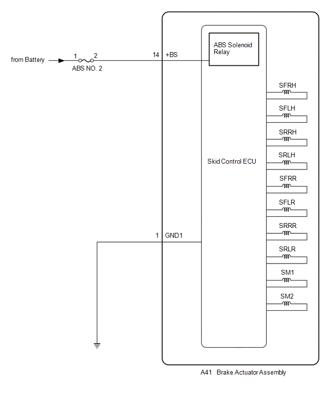
The ABS solenoid relay is built into the skid control ECU in the brake actuator assembly.
The ABS solenoid relay supplies power to the holding solenoid and reduction solenoid.
The solenoid relay is turned on 1.5 seconds after the engine switch is turned on (IG), and is turned off if an open or short in the solenoid is detected by self-diagnosis performed when the vehicle is starting off.
| DTC No. | Detection Item | DTC Detection Condition | Trouble Area |
|---|---|---|---|
| C143A7E | ABS Solenoid Control Module Actuator Stuck On | When voltage at terminal +BS is 9.5 V or higher, solenoid relay is OFF, relay contact is ON continuously for 4.5 seconds or more. | Skid control ECU (brake actuator assembly) |
| C143A7F | ABS Solenoid Control Module Actuator Stuck Off | When voltage at terminal +BS is 9.5 V or higher and solenoid relay is ON, relay contact is OFF continuously for 0.22 seconds or more. |
|
WIRING DIAGRAM
CAUTION / NOTICE / HINT
NOTICE:
- Inspect the fuses for circuits related to this system before performing the following procedure.
-
After replacing the skid control ECU (brake actuator assembly), perform "Calibration".
Click here
.gif)
HINT:
When C137BA2 and/or C137BA3 is output together with C143A7E and/or C143A7F, inspect and repair the trouble areas indicated by C137BA2 and/or C137BA3 first.
for C137BA2: Click here
for C137BA3: Click here
PROCEDURE
| 1. | CHECK HARNESS AND CONNECTOR (+BS TERMINAL) |
| (a) Make sure that there is no looseness at the locking part and the connecting part of the connectors. OK: The connector is securely connected. |
|
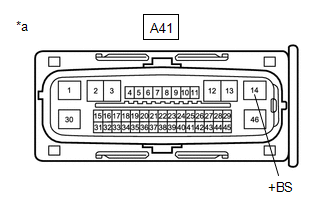
(b) Disconnect the A41 skid control ECU (brake actuator assembly) connector.
(c) Check both the connector case and the terminals for deformation and corrosion.
OK:
No deformation or corrosion.
(d) Measure the voltage according to the value(s) in the table below.
Standard Voltage:
| Tester Connection | Condition | Specified Condition |
|---|---|---|
| A41-14 (+BS) - Body ground | Always | 11 to 14 V |
| NG | .gif) | REPAIR OR REPLACE HARNESS OR CONNECTOR |
|
.gif)
| 2. | CHECK HARNESS AND CONNECTOR (GND1 TERMINAL) |
(a) Measure the resistance according to the value(s) in the table below.
Standard Resistance:
| Tester Connection | Condition | Specified Condition |
|---|---|---|
| A41-1 (GND1) - Body ground | 1 minute or more after disconnecting the cable from the negative (-) battery terminal | Below 1 Ω |
| NG | | REPAIR OR REPLACE HARNESS OR CONNECTOR |
|
| 3. | CLEAR DTC |
(a) Reconnect the A41 skid control ECU (brake actuator assembly) connector.
(b) Connect the Techstream to the DLC3.
(c) Turn the engine switch on (IG).
(d) Operate the Techstream to clear the codes. Enter the following menus: Chassis / Brake/EPB / Trouble Codes.
Chassis > Brake/EPB > Clear DTCs(e) Press the DTC clear button.
(f) Turn the engine switch off.
|
| 4. | RECONFIRM DTC |
(a) Start the engine.
(b) Perform a road test.
(c) Read the DTCs following the prompts on the Techstream. Enter the following menus: Chassis / Brake/EPB / Trouble Codes.
Chassis > Brake/EPB > Trouble Codes(d) Check if the same DTC is output.
| Result | Proceed to |
|---|---|
| DTCs C143A7E and C143A7F are not output. | A |
| DTCs C143A7E and/or C143A7F are output. | B |
HINT:
- If a speed signal of 20 km/h (12 mph) or more is input to the skid control ECU (brake actuator assembly) with the engine switch on (IG) and the stop light switch assembly off, the ECU performs self-diagnosis of the solenoid circuit.
- If the normal system code is output (no DTCs are output), slightly jiggle the connectors, wire harnesses, and fuses of the skid control ECU (brake actuator assembly).
- If any DTCs are output while jiggling a connector or wire harness of the skid control ECU (brake actuator assembly), inspect and repair the connector or wire harness.
- If no DTCs were output when reconfirming DTCs, checking for intermittent problems is necessary because it is suspected that the original DTCs were stored due to the poor connection of a connector terminal.
| A | | USE SIMULATION METHOD TO CHECK |
| B | | REPLACE BRAKE ACTUATOR ASSEMBLY |
 Stop Lamp Relay Actuator Stuck Off (C13807F)
DESCRIPTION Refer to DTC C13807E. Click here DTC No. Detection Item DTC Detection Condition Trouble Area C13807F Stop Lamp Relay Actuator Stuck Off Either of the following is detect ...
 ABS Pump Motor Actuator Stuck (C142771)
DESCRIPTION DTC No. Detection Item DTC Detection Condition Trouble Area C142771 ABS Pump Motor Actuator Stuck Actuator pump motor does not operate properly.
Wire harness and conn ...
Other materials:
Lexus RX (RX 350L, RX450h) 2016-2026 Repair Manual > Clearance Warning Ecu: Components
COMPONENTS ILLUSTRATION *A w/ Panoramic View Monitor System - - *1 COWL SIDE TRIM BOARD RH *2 ECU INTEGRATION BOX RH *3 FRONT DOOR SCUFF PLATE RH *4 GLOVE COMPARTMENT DOOR ASSEMBLY *5 INSTRUMENT PANEL GARNISH RH *6 LOWER NO. 1 INSTRUMENT PANEL FINISH PANEL ...
Lexus RX (RX 350L, RX450h) 2016-2026 Repair Manual > Airbag System: Lost Communication with Front Door Pressure Sensor LH (B167B,B167C)
DESCRIPTION The side collision sensor LH circuit (bus 1) consists of the airbag sensor assembly, door side airbag sensor LH and rear airbag sensor LH. The door side airbag sensor LH and rear airbag sensor LH detect impacts to the vehicle and send signals to the airbag sensor assembly to determine if ...
Lexus RX (RX 350L, RX450h) 2016-{YEAR} Owners Manual
- For your information
- Pictorial index
- For safety and security
- Instrument cluster
- Operation of each component
- Driving
- Lexus Display Audio system
- Interior features
- Maintenance and care
- When trouble arises
- Vehicle specifications
- For owners
Lexus RX (RX 350L, RX450h) 2016-{YEAR} Repair Manual

0.011