Lexus RX (RX 350L, RX450h) 2016-2026 Repair Manual: Stop Lamp Relay Actuator Stuck Off (C13807F)
DESCRIPTION
Refer to DTC C13807E.
Click here .gif)
| DTC No. | Detection Item | DTC Detection Condition | Trouble Area |
|---|---|---|---|
| C13807F | Stop Lamp Relay Actuator Stuck Off | Either of the following is detected:
|
|
| Vehicle Condition | |||
|---|---|---|---|
| Pattern 1 | Pattern 2 | ||
| Diagnosis Condition | IG1 terminal voltage exceeds 10 V and +BS terminal voltage is from 9.5 to 17.4 V | ○ | - |
| IG1 terminal voltage exceeds 10 V and +BS terminal voltage is 9.5 V or higher | - | ○ | |
| Malfunction Status | Stop light drive output (STPO) is ON, STP is OFF and STP2 is OFF | ○ | - |
| Stop light drive output (STPO) is OFF, STP is ON and STP2 is OFF | - | ○ | |
| Detection Time | 2 seconds or more. | 5 seconds or more. | |
| Number of Trips | 1 trip | 1 trip | |
HINT:
DTC will be output when conditions for either of the patterns in the table above are met.
WIRING DIAGRAM
Refer to DTC C13807E.
Click here
CAUTION / NOTICE / HINT
NOTICE:
After replacing the skid control ECU (brake actuator assembly), perform "Calibration".
Click here
PROCEDURE
| 1. | CHECK STOP LIGHT OPERATION |
(a) Check that the stop lights come on when the brake pedal is depressed.
OK:
The stop lights illuminate.
| NG | .gif) | GO TO STEP 6 |
|

| 2. | PERFORM ACTIVE TEST USING TECHSTREAM (STOP LAMP RELAY) |
(a) Connect the Techstream to the DLC3.
(b) Enter the following menus: Chassis / Brake/EPB / Active Test.
Chassis > Brake/EPB > Active Test| Tester Display | Measurement Item | Control Range | Restrict Condition | Diagnostic Note |
|---|---|---|---|---|
| Stop Lamp Relay | Semiconductor PWR integration ECU (STPO terminal output) | OFF / ON | Vehicle condition: Vehicle stopped HINT: To protect this Actuator and Solenoid, this test will only last 5 seconds. | - |
| Tester Display |
|---|
| Stop Lamp Relay |
(c) According to the display on the Techstream, perform the Active Test and check the operation of the stop lights.
OK:
Stop lights turn on in accordance with the Active Test.
| NG | | GO TO STEP 4 |
|
| 3. | CHECK HARNESS AND CONNECTOR (STOP LIGHT SIGNAL INPUT CIRCUIT) |
| (a) Turn the engine switch off. |
|
(b) Make sure that there is no looseness at the locking part and the connecting part of the connectors.
OK:
The connector is securely connected.
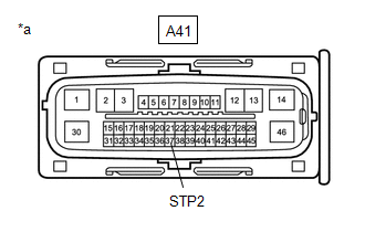
(c) Disconnect the A41 skid control ECU (brake actuator assembly) connector.
(d) Check both the connector case and the terminals for deformation and corrosion.
OK:
No deformation or corrosion.
(e) Measure the voltage according to the value(s) in the table below.
Standard Voltage:
| Tester Connection | Condition | Specified Condition |
|---|---|---|
| A41-37 (STP2) - Body ground | Brake pedal depressed | 11 to 14 V |
| OK | | REPLACE BRAKE ACTUATOR ASSEMBLY |
| NG | | REPAIR OR REPLACE HARNESS OR CONNECTOR |
| 4. | CHECK HARNESS AND CONNECTOR (STOP LIGHT ILLUMINATION OUTPUT CIRCUIT) |
| (a) Turn the engine switch off. |
|
.png)
(b) Make sure that there is no looseness at the locking part and the connecting part of the connectors.
OK:
The connector is securely connected.
(c) Disconnect the A41 skid control ECU (brake actuator assembly) connector.
(d) Check both the connector case and the terminals for deformation and corrosion.
OK:
No deformation or corrosion.
(e) Turn the engine switch on (IG).
(f) Measure the voltage according to the value(s) in the table below.
Standard Voltage:
| Tester Connection | Condition | Specified Condition |
|---|---|---|
| A41-32 (STPO) - Body ground | Engine switch on (IG) | 11 to 14 V |
| OK | | REPLACE BRAKE ACTUATOR ASSEMBLY |
|
| 5. | CHECK HARNESS AND CONNECTOR (SEMICONDUCTOR PWR INTEGRATION ECU - BRAKE ACTUATOR ASSEMBLY) |
(a) Turn the engine switch off.
(b) Make sure that there is no looseness at the locking part and the connecting part of the connectors.
OK:
The connector is securely connected.
(c) Disconnect the 1D semiconductor PWR integration ECU connector.
(d) Check both the connector case and the terminals for deformation and corrosion.
OK:
No deformation or corrosion.
(e) Measure the resistance according to the value(s) in the table below.
Standard Resistance:
| Tester Connection | Condition | Specified Condition |
|---|---|---|
| 1D-3 (ACC) - A41-32 (STPO) | Always | Below 1 Ω |
| OK | | REPLACE SEMICONDUCTOR PWR INTEGRATION ECU |
| NG | | REPAIR OR REPLACE HARNESS OR CONNECTOR |
| 6. | READ VALUE USING TECHSTREAM (STOP LIGHT RELAY) |
(a) Turn the engine switch off.
(b) Make sure that there is no looseness at the locking part and the connecting part of the connectors.
OK:
The connector is securely connected.
(c) Disconnect the S31 rear combination light assembly LH connector.
(d) Check both the connector case and the terminals for deformation and corrosion.
OK:
No deformation or corrosion.
(e) Turn the engine switch on (IG).
(f) Connect the Techstream to the DLC3.
(g) Enter the following menus: Chassis / Brake/EPB / Data List.
Chassis > Brake/EPB > Data List| Tester Display | Measurement Item | Range | Normal Condition | Diagnostic Note |
|---|---|---|---|---|
| Stop Light Relay | Semiconductor PWR integration ECU (STP2 terminal input) | OFF / ON | OFF: Semiconductor PWR integration ECU (STP2 terminal input) OFF ON: Semiconductor PWR integration ECU (STP2 terminal input) ON | HINT: The stop light state is determined using the voltage at terminal STP2 |
| Tester Display |
|---|
| Stop Light Relay |
(h) With the brake pedal released, check the value of Data List item "Stop Light Relay".
| Result | Proceed to |
|---|---|
| The value of Data List item "Stop Light Relay" is "OFF" | A |
| The value of Data List item "Stop Light Relay" is "ON" | B |
| A | | GO TO LIGHTING SYSTEM (REAR COMBINATION LIGHT ASSEMBLY LH (STOP LIGHT CIRCUIT)) |
|
| 7. | READ VALUE USING TECHSTREAM (STOP LIGHT RELAY) |
(a) Turn the engine switch off.
(b) Make sure that there is no looseness at the locking part and the connecting part of the connectors.
OK:
The connector is securely connected.
(c) Disconnect the S33 rear combination light assembly RH connector.
(d) Check both the connector case and the terminals for deformation and corrosion.
OK:
No deformation or corrosion.
(e) Turn the engine switch on (IG).
(f) Connect the Techstream to the DLC3.
(g) Enter the following menus: Chassis / Brake/EPB / Data List.
Chassis > Brake/EPB > Data List| Tester Display | Measurement Item | Range | Normal Condition | Diagnostic Note |
|---|---|---|---|---|
| Stop Light Relay | Semiconductor PWR integration ECU (STP2 terminal input) | OFF / ON | OFF: Semiconductor PWR integration ECU (STP2 terminal input) OFF ON: Semiconductor PWR integration ECU (STP2 terminal input) ON | HINT: The stop light state is determined using the voltage at terminal STP2 |
| Tester Display |
|---|
| Stop Light Relay |
(h) With the brake pedal released, check the value of Data List item "Stop Light Relay".
| Result | Proceed to |
|---|---|
| The value of Data List item "Stop Light Relay" is "OFF" | A |
| The value of Data List item "Stop Light Relay" is "ON" | B |
| A | | GO TO LIGHTING SYSTEM (REAR COMBINATION LIGHT ASSEMBLY RH (STOP LIGHT CIRCUIT)) |
|
| 8. | READ VALUE USING TECHSTREAM (STOP LIGHT RELAY) |
(a) Turn the engine switch off.
(b) Make sure that there is no looseness at the locking part and the connecting part of the connectors.
OK:
The connector is securely connected.
(c) Disconnect the Z21 rear light assembly LH connector.
(d) Check both the connector case and the terminals for deformation and corrosion.
OK:
No deformation or corrosion.
(e) Turn the engine switch on (IG).
(f) Connect the Techstream to the DLC3.
(g) Enter the following menus: Chassis / Brake/EPB / Data List.
Chassis > Brake/EPB > Data List| Tester Display | Measurement Item | Range | Normal Condition | Diagnostic Note |
|---|---|---|---|---|
| Stop Light Relay | Semiconductor PWR integration ECU (STP2 terminal input) | OFF / ON | OFF: Semiconductor PWR integration ECU (STP2 terminal input) OFF ON: Semiconductor PWR integration ECU (STP2 terminal input) ON | HINT: The stop light state is determined using the voltage at terminal STP2 |
| Tester Display |
|---|
| Stop Light Relay |
(h) With the brake pedal released, check the value of Data List item "Stop Light Relay".
| Result | Proceed to |
|---|---|
| The value of Data List item "Stop Light Relay" is "OFF" | A |
| The value of Data List item "Stop Light Relay" is "ON" | B |
| A | | GO TO LIGHTING SYSTEM (REAR LIGHT ASSEMBLY LH (STOP LIGHT CIRCUIT)) |
|
| 9. | READ VALUE USING TECHSTREAM (STOP LIGHT RELAY) |
(a) Turn the engine switch off.
(b) Make sure that there is no looseness at the locking part and the connecting part of the connectors.
OK:
The connector is securely connected.
(c) Disconnect the Z20 rear light assembly RH connector.
(d) Check both the connector case and the terminals for deformation and corrosion.
OK:
No deformation or corrosion.
(e) Turn the engine switch on (IG).
(f) Connect the Techstream to the DLC3.
(g) Enter the following menus: Chassis / Brake/EPB / Data List.
Chassis > Brake/EPB > Data List| Tester Display | Measurement Item | Range | Normal Condition | Diagnostic Note |
|---|---|---|---|---|
| Stop Light Relay | Semiconductor PWR integration ECU (STP2 terminal input) | OFF / ON | OFF: Semiconductor PWR integration ECU (STP2 terminal input) OFF ON: Semiconductor PWR integration ECU (STP2 terminal input) ON | HINT: The stop light state is determined using the voltage at terminal STP2 |
| Tester Display |
|---|
| Stop Light Relay |
(h) With the brake pedal released, check the value of Data List item "Stop Light Relay".
| Result | Proceed to |
|---|---|
| The value of Data List item "Stop Light Relay" is "OFF" | A |
| The value of Data List item "Stop Light Relay" is "ON" | B |
| A | | GO TO LIGHTING SYSTEM (REAR LIGHT ASSEMBLY RH (STOP LIGHT CIRCUIT)) |
|
| 10. | READ VALUE USING TECHSTREAM (STOP LIGHT RELAY) |
(a) Turn the engine switch off.
(b) Make sure that there is no looseness at the locking part and the connecting part of the connectors.
OK:
The connector is securely connected.
(c) Disconnect the v1 center stop light assembly connector.
(d) Check both the connector case and the terminals for deformation and corrosion.
OK:
No deformation or corrosion.
(e) Turn the engine switch on (IG).
(f) Connect the Techstream to the DLC3.
(g) Enter the following menus: Chassis / Brake/EPB / Data List.
Chassis > Brake/EPB > Data List| Tester Display | Measurement Item | Range | Normal Condition | Diagnostic Note |
|---|---|---|---|---|
| Stop Light Relay | Semiconductor PWR integration ECU (STP2 terminal input) | OFF / ON | OFF: Semiconductor PWR integration ECU (STP2 terminal input) OFF ON: Semiconductor PWR integration ECU (STP2 terminal input) ON | HINT: The stop light state is determined using the voltage at terminal STP2 |
| Tester Display |
|---|
| Stop Light Relay |
(h) With the brake pedal released, check the value of Data List item "Stop Light Relay".
| Result | Proceed to |
|---|---|
| The value of Data List item "Stop Light Relay" is "OFF" | A |
| The value of Data List item "Stop Light Relay" is "ON" | B |
| A | | REPLACE CENTER STOP LIGHT ASSEMBLY |
|
| 11. | CHECK HARNESS AND CONNECTOR (SEMICONDUCTOR PWR INTEGRATION ECU - BRAKE ACTUATOR ASSEMBLY) |
| (a) Turn the engine switch off. |
|
(b) Make sure that there is no looseness at the locking part and the connecting part of the connectors.
OK:
The connector is securely connected.
(c) Disconnect the A41 skid control ECU (brake actuator assembly) connector.
(d) Check both the connector case and the terminals for deformation and corrosion.
OK:
No deformation or corrosion.
(e) Measure the voltage according to the value(s) in the table below.
Standard Voltage:
| Tester Connection | Condition | Specified Condition |
|---|---|---|
| A41-37 (STP2) - Body ground | Brake pedal depressed | 11 to 14 V |
| OK | | REPLACE BRAKE ACTUATOR ASSEMBLY |
|
| 12. | CHECK HARNESS AND CONNECTOR (SEMICONDUCTOR PWR INTEGRATION ECU - BRAKE ACTUATOR ASSEMBLY) |
(a) Make sure that there is no looseness at the locking part and the connecting part of the connectors.
OK:
The connector is securely connected.
(b) Disconnect the 1D semiconductor PWR integration ECU connector.
(c) Check both the connector case and the terminals for deformation and corrosion.
OK:
No deformation or corrosion.
(d) Measure the resistance according to the value(s) in the table below.
Standard Resistance:
| Tester Connection | Condition | Specified Condition |
|---|---|---|
| 1D-10 (STP) - A41-11 (STP) | Always | Below 1 Ω |
| NG | | REPAIR OR REPLACE HARNESS OR CONNECTOR |
|
| 13. | CHECK HARNESS AND CONNECTOR (SEMICONDUCTOR PWR INTEGRATION ECU - BRAKE ACTUATOR ASSEMBLY) |
(a) Make sure that there is no looseness at the locking part and the connecting part of the connectors.
OK:
The connector is securely connected.
(b) Disconnect the 1F semiconductor PWR integration ECU connector.
(c) Check both the connector case and the terminals for deformation and corrosion.
OK:
No deformation or corrosion.
(d) Measure the resistance according to the value(s) in the table below.
Standard Resistance:
| Tester Connection | Condition | Specified Condition |
|---|---|---|
| 1F-9 (OUT) - A41-37 (STP2) | Always | Below 1 Ω |
| 1F-9 (OUT) or A41-37 (STP2) - Body ground and other terminals | Always | 10 kΩ or higher |
| OK | | REPLACE SEMICONDUCTOR PWR INTEGRATION ECU |
| NG | | REPAIR OR REPLACE HARNESS OR CONNECTOR |
 Stop Lamp Relay Actuator Stuck On (C13807E)
DESCRIPTION When any of the following conditions are met, the skid control ECU (brake actuator assembly) sets the drive output (STPO) ON which operates the stop light control relay (stop light switch ...
 ABS Solenoid Control Module Actuator Stuck On (C143A7E,C143A7F)
DESCRIPTION The ABS solenoid relay is built into the skid control ECU in the brake actuator assembly. The ABS solenoid relay supplies power to the holding solenoid and reduction solenoid. The solenoid ...
Other materials:
Lexus RX (RX 350L, RX450h) 2016-2026 Repair Manual > Axle And Differential: Front Axle Hub Bolt
ComponentsCOMPONENTS ILLUSTRATION *1 FRONT AXLE HUB BOLT *2 FRONT DISC *3 FRONT DISC BRAKE CALIPER ASSEMBLY - - Tightening torque for "Major areas involving basic vehicle performance such as moving/turning/stopping" : N*m (kgf*cm, ft.*lbf) ● Non-reusable part Repl ...
Lexus RX (RX 350L, RX450h) 2016-2026 Repair Manual > Road Sign Assist System: How To Proceed With Troubleshooting
CAUTION / NOTICE / HINT HINT:
Before performing troubleshooting for the road sign assist system, make sure that the pre-collision system and lane control system are not malfunctioning.
Pre-collision system: Click here Lane control system: Click here
Perform the following procedure to troubl ...
Lexus RX (RX 350L, RX450h) 2016-{YEAR} Owners Manual
- For your information
- Pictorial index
- For safety and security
- Instrument cluster
- Operation of each component
- Driving
- Lexus Display Audio system
- Interior features
- Maintenance and care
- When trouble arises
- Vehicle specifications
- For owners
Lexus RX (RX 350L, RX450h) 2016-{YEAR} Repair Manual

0.0096