Lexus RX (RX 350L, RX450h) 2016-2026 Repair Manual: Stop Lamp Relay Actuator Stuck On (C13807E)
DESCRIPTION
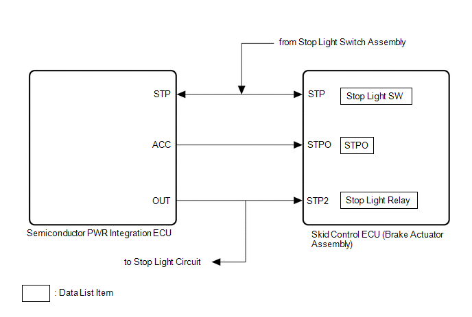
When any of the following conditions are met, the skid control ECU (brake actuator assembly) sets the drive output (STPO) ON which operates the stop light control relay (stop light switch assembly) and turns on the stop lights.
- Pre-collision brake is operating.
- The dynamic radar cruise control system is operating and is applying the brakes.
- Secondary collision brake is operating.
- Brake hold is operating.
- The parking brake is engaged while the vehicle is being driven.
| DTC No. | Detection Item | DTC Detection Condition | Trouble Area |
|---|---|---|---|
| C13807E | Stop Lamp Relay Actuator Stuck On | When the IG1 terminal voltage exceeds 10 V and the +BS terminal voltage is 9.5 V or higher, stop light drive output (STPO) is OFF, STP is OFF and STP2 is ON continuously for 5 seconds or more. |
|
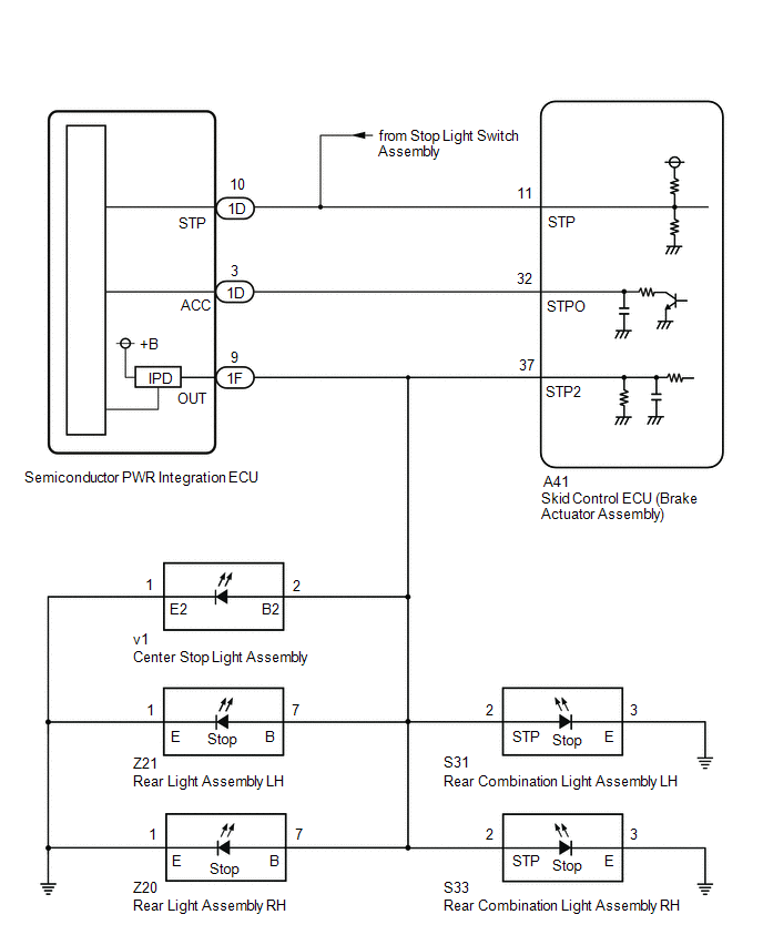
WIRING DIAGRAM
CAUTION / NOTICE / HINT
NOTICE:
After replacing the skid control ECU (brake actuator assembly), perform "Calibration".
Click here .gif)
PROCEDURE
| 1. | CHECK STOP LIGHT ILLUMINATION STATUS |
(a) Make sure that there is no looseness at the locking part and the connecting part of the connectors.
OK:
The connector is securely connected.
(b) Disconnect the 1D semiconductor PWR integration ECU connector.
(c) Check both the connector case and the terminals for deformation and corrosion.
OK:
No deformation or corrosion.
(d) Turn the engine switch on (IG).
(e) Check the illumination status of the brake lights.
| Result | Proceed to |
|---|---|
| The stop lights are illuminated. | A |
| The stop lights are not illuminated. | B |
| B | .gif) | GO TO STEP 9 |
|
.gif)
| 2. | READ VALUE USING TECHSTREAM (STOP LIGHT RELAY) |
(a) Turn the engine switch off.
(b) Reconnect the 1D semiconductor PWR integration ECU connector.
(c) Make sure that there is no looseness at the locking part and the connecting part of the connectors.
OK:
The connector is securely connected.
(d) Disconnect the 1F semiconductor PWR integration ECU connector.
(e) Check both the connector case and the terminals for deformation and corrosion.
OK:
No deformation or corrosion.
(f) Turn the engine switch on (IG).
(g) Connect the Techstream to the DLC3.
(h) Enter the following menus: Chassis / Brake/EPB / Data List.
Chassis > Brake/EPB > Data List| Tester Display | Measurement Item | Range | Normal Condition | Diagnostic Note |
|---|---|---|---|---|
| Stop Light Relay | Semiconductor PWR integration ECU (STP2 terminal input) | OFF / ON | OFF: Semiconductor PWR integration ECU (STP2 terminal input) OFF ON: Semiconductor PWR integration ECU (STP2 terminal input) ON | HINT: The stop light state is determined using the voltage at terminal STP2 |
| Tester Display |
|---|
| Stop Light Relay |
(i) With the brake pedal released, check the value of Data List item "Stop Light Relay".
| Result | Proceed to |
|---|---|
| The value of Data List item "Stop Light Relay" is "OFF" | A |
| The value of Data List item "Stop Light Relay" is "ON" | B |
| A | | REPLACE SEMICONDUCTOR PWR INTEGRATION ECU |
|
| 3. | READ VALUE USING TECHSTREAM (STOP LIGHT RELAY) |
(a) Turn the engine switch off.
(b) Make sure that there is no looseness at the locking part and the connecting part of the connectors.
OK:
The connector is securely connected.
(c) Disconnect the S31 rear combination light assembly LH connector.
(d) Check both the connector case and the terminals for deformation and corrosion.
OK:
No deformation or corrosion.
(e) Turn the engine switch on (IG).
(f) Connect the Techstream to the DLC3.
(g) Enter the following menus: Chassis / Brake/EPB / Data List.
Chassis > Brake/EPB > Data List| Tester Display | Measurement Item | Range | Normal Condition | Diagnostic Note |
|---|---|---|---|---|
| Stop Light Relay | Semiconductor PWR integration ECU (STP2 terminal input) | OFF / ON | OFF: Semiconductor PWR integration ECU (STP2 terminal input) OFF ON: Semiconductor PWR integration ECU (STP2 terminal input) ON | HINT: The stop light state is determined using the voltage at terminal STP2 |
| Tester Display |
|---|
| Stop Light Relay |
(h) With the brake pedal released, check the value of Data List item "Stop Light Relay".
| Result | Proceed to |
|---|---|
| The value of Data List item "Stop Light Relay" is "OFF" | A |
| The value of Data List item "Stop Light Relay" is "ON" | B |
| A | | GO TO LIGHTING SYSTEM (REAR COMBINATION LIGHT ASSEMBLY LH (STOP LIGHT CIRCUIT)) |
|
| 4. | READ VALUE USING TECHSTREAM (STOP LIGHT RELAY) |
(a) Turn the engine switch off.
(b) Make sure that there is no looseness at the locking part and the connecting part of the connectors.
OK:
The connector is securely connected.
(c) Disconnect the S33 rear combination light assembly RH connector.
(d) Check both the connector case and the terminals for deformation and corrosion.
OK:
No deformation or corrosion.
(e) Turn the engine switch on (IG).
(f) Connect the Techstream to the DLC3.
(g) Enter the following menus: Chassis / Brake/EPB / Data List.
Chassis > Brake/EPB > Data List| Tester Display | Measurement Item | Range | Normal Condition | Diagnostic Note |
|---|---|---|---|---|
| Stop Light Relay | Semiconductor PWR integration ECU (STP2 terminal input) | OFF / ON | OFF: Semiconductor PWR integration ECU (STP2 terminal input) OFF ON: Semiconductor PWR integration ECU (STP2 terminal input) ON | HINT: The stop light state is determined using the voltage at terminal STP2 |
| Tester Display |
|---|
| Stop Light Relay |
(h) With the brake pedal released, check the value of Data List item "Stop Light Relay".
| Result | Proceed to |
|---|---|
| The value of Data List item "Stop Light Relay" is "OFF" | A |
| The value of Data List item "Stop Light Relay" is "ON" | B |
| A | | GO TO LIGHTING SYSTEM (REAR COMBINATION LIGHT ASSEMBLY RH (STOP LIGHT CIRCUIT)) |
|
| 5. | READ VALUE USING TECHSTREAM (STOP LIGHT RELAY) |
(a) Turn the engine switch off.
(b) Make sure that there is no looseness at the locking part and the connecting part of the connectors.
OK:
The connector is securely connected.
(c) Disconnect the Z21 rear light assembly LH connector.
(d) Check both the connector case and the terminals for deformation and corrosion.
OK:
No deformation or corrosion.
(e) Turn the engine switch on (IG).
(f) Connect the Techstream to the DLC3.
(g) Enter the following menus: Chassis / Brake/EPB / Data List.
Chassis > Brake/EPB > Data List| Tester Display | Measurement Item | Range | Normal Condition | Diagnostic Note |
|---|---|---|---|---|
| Stop Light Relay | Semiconductor PWR integration ECU (STP2 terminal input) | OFF / ON | OFF: Semiconductor PWR integration ECU (STP2 terminal input) OFF ON: Semiconductor PWR integration ECU (STP2 terminal input) ON | HINT: The stop light state is determined using the voltage at terminal STP2 |
| Tester Display |
|---|
| Stop Light Relay |
(h) With the brake pedal released, check the value of Data List item "Stop Light Relay".
| Result | Proceed to |
|---|---|
| The value of Data List item "Stop Light Relay" is "OFF" | A |
| The value of Data List item "Stop Light Relay" is "ON" | B |
| A | | GO TO LIGHTING SYSTEM (REAR LIGHT ASSEMBLY LH (STOP LIGHT CIRCUIT)) |
|
| 6. | READ VALUE USING TECHSTREAM (STOP LIGHT RELAY) |
(a) Turn the engine switch off.
(b) Make sure that there is no looseness at the locking part and the connecting part of the connectors.
OK:
The connector is securely connected.
(c) Disconnect the Z20 rear light assembly RH connector.
(d) Check both the connector case and the terminals for deformation and corrosion.
OK:
No deformation or corrosion.
(e) Turn the engine switch on (IG).
(f) Connect the Techstream to the DLC3.
(g) Enter the following menus: Chassis / Brake/EPB / Data List.
Chassis > Brake/EPB > Data List| Tester Display | Measurement Item | Range | Normal Condition | Diagnostic Note |
|---|---|---|---|---|
| Stop Light Relay | Semiconductor PWR integration ECU (STP2 terminal input) | OFF / ON | OFF: Semiconductor PWR integration ECU (STP2 terminal input) OFF ON: Semiconductor PWR integration ECU (STP2 terminal input) ON | HINT: The stop light state is determined using the voltage at terminal STP2 |
| Tester Display |
|---|
| Stop Light Relay |
(h) With the brake pedal released, check the value of Data List item "Stop Light Relay".
| Result | Proceed to |
|---|---|
| The value of Data List item "Stop Light Relay" is "OFF" | A |
| The value of Data List item "Stop Light Relay" is "ON" | B |
| A | | GO TO LIGHTING SYSTEM (REAR LIGHT ASSEMBLY RH (STOP LIGHT CIRCUIT)) |
|
| 7. | READ VALUE USING TECHSTREAM (STOP LIGHT RELAY) |
(a) Turn the engine switch off.
(b) Make sure that there is no looseness at the locking part and the connecting part of the connectors.
OK:
The connector is securely connected.
(c) Disconnect the v1 center stop light assembly connector.
(d) Check both the connector case and the terminals for deformation and corrosion.
OK:
No deformation or corrosion.
(e) Turn the engine switch on (IG).
(f) Connect the Techstream to the DLC3.
(g) Enter the following menus: Chassis / Brake/EPB / Data List.
Chassis > Brake/EPB > Data List| Tester Display | Measurement Item | Range | Normal Condition | Diagnostic Note |
|---|---|---|---|---|
| Stop Light Relay | Semiconductor PWR integration ECU (STP2 terminal input) | OFF / ON | OFF: Semiconductor PWR integration ECU (STP2 terminal input) OFF ON: Semiconductor PWR integration ECU (STP2 terminal input) ON | HINT: The stop light state is determined using the voltage at terminal STP2 |
| Tester Display |
|---|
| Stop Light Relay |
(h) With the brake pedal released, check the value of Data List item "Stop Light Relay".
| Result | Proceed to |
|---|---|
| The value of Data List item "Stop Light Relay" is "OFF" | A |
| The value of Data List item "Stop Light Relay" is "ON" | B |
| A | | REPLACE CENTER STOP LIGHT ASSEMBLY |
|
| 8. | CHECK HARNESS AND CONNECTOR (SEMICONDUCTOR PWR INTEGRATION ECU - BRAKE ACTUATOR ASSEMBLY) |
| (a) Turn the engine switch off. |
|
(b) Make sure that there is no looseness at the locking part and the connecting part of the connectors.
OK:
The connector is securely connected.
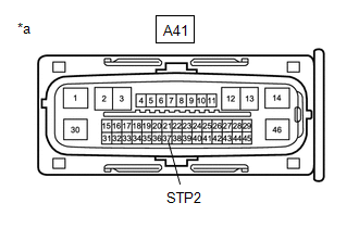
(c) Disconnect the A41 skid control ECU (brake actuator assembly) connector.
(d) Check both the connector case and the terminals for deformation and corrosion.
OK:
No deformation or corrosion.
(e) Turn the engine switch on (IG).
(f) Measure the voltage according to the value(s) in the table below.
Standard Voltage:
| Tester Connection | Condition | Specified Condition |
|---|---|---|
| A41-37 (STP2) - Body ground | Engine switch on (IG) | 0 V |
| OK | | REPLACE BRAKE ACTUATOR ASSEMBLY |
| NG | | REPAIR OR REPLACE HARNESS OR CONNECTOR |
| 9. | CHECK HARNESS AND CONNECTOR (SEMICONDUCTOR PWR INTEGRATION ECU - BRAKE ACTUATOR ASSEMBLY) |
(a) Turn the engine switch off.
(b) Make sure that there is no looseness at the locking part and the connecting part of the connectors.
OK:
The connector is securely connected.
(c) Disconnect the A41 skid control ECU (brake actuator assembly) connector.
(d) Check both the connector case and the terminals for deformation and corrosion.
OK:
No deformation or corrosion.
(e) Measure the resistance according to the value(s) in the table below.
Standard Resistance:
| Tester Connection | Condition | Specified Condition |
|---|---|---|
| 1D-3 (ACC) or A41-32 (STPO) - Body ground and other terminals | Always | 10 kΩ or higher |
| OK | | REPLACE BRAKE ACTUATOR ASSEMBLY |
| NG | | REPAIR OR REPLACE HARNESS OR CONNECTOR |
 Brake System Control Module "A" System Voltage System Voltage High (C137BA3)
DESCRIPTION If a malfunction is detected in the power supply circuit, the skid control ECU (brake actuator assembly) stores this DTC and the fail-safe function prohibits ABS operation. This DTC is sto ...
 Stop Lamp Relay Actuator Stuck Off (C13807F)
DESCRIPTION Refer to DTC C13807E. Click here DTC No. Detection Item DTC Detection Condition Trouble Area C13807F Stop Lamp Relay Actuator Stuck Off Either of the following is detect ...
Other materials:
Lexus RX (RX 350L, RX450h) 2016-2026 Repair Manual > Combination Switch: Inspection
INSPECTION PROCEDURE 1. INSPECT COMBINATION SWITCH ASSEMBLY (a) Inspect the NORMAL or NORMAL CUSTOMIZE mode switch: (1) Measure the resistance according to the value(s) in the table below. Standard Resistance: Tester Connection Condition Specified Condition 8 (B) - 1 (GND) Combinati ...
Lexus RX (RX 350L, RX450h) 2016-2026 Repair Manual > Outer Rear View Mirror: Reassembly
REASSEMBLY CAUTION / NOTICE / HINT HINT:
Use the same procedure for the RH side and LH side.
The following procedure is for the LH side.
PROCEDURE 1. INSTALL OUTER MIRROR RETRACTOR LH (w/ Power Retract Mirror) (a) Install a new frame sub-assembly to the support as shown in the illustration. ...
Lexus RX (RX 350L, RX450h) 2016-{YEAR} Owners Manual
- For your information
- Pictorial index
- For safety and security
- Instrument cluster
- Operation of each component
- Driving
- Lexus Display Audio system
- Interior features
- Maintenance and care
- When trouble arises
- Vehicle specifications
- For owners
Lexus RX (RX 350L, RX450h) 2016-{YEAR} Repair Manual

0.0122