Lexus RX (RX 350L, RX450h) 2016-2026 Repair Manual: System Description
SYSTEM DESCRIPTION
GENERAL
The air conditioning system has the following controls.
| Control | Outline |
|---|---|
| Neural Network Control | This control is capable of performing complex control by artificially simulating the information processing method of the nervous system of living organisms in order to establish a complex input/output relationship similar to that of a human brain. |
| Outlet Air Temperature Control | Based on the temperature set by the temperature control dial, neural network control calculates outlet air temperature based on input signals from various sensors. |
| Dual Control | The temperature settings for the driver and front passenger are controlled independently in order to provide separate vehicle interior temperatures for the right and left sides of the vehicle. Thus, air conditioning that accommodates the occupants' preferences has been realized. |
| Blower Control | Controls the blower motor in accordance with the airflow volume that has been calculated by neural network control based on input signals from various sensors. |
| Air Outlet Control | Automatically switches the air outlets in accordance with the outlet mode that has been calculated by neural network control. |
| In accordance with the engine coolant temperature, ambient air temperature, amount of sunlight, required blower, outlet temperature and vehicle speed conditions, this control automatically switches the blower outlet to foot/defroster mode to prevent the windows from becoming fogged up when the ambient air temperature is low. | |
| Air Inlet Control | Automatically controls the air inlet control damper to help achieve the calculated outlet air temperature that is required. |
| Drives the air inlet control servo motor according to the operation of the air inlet control switch and moves the dampers to the fresh or recirculation position. | |
| Compressor Control | Through the calculation of the target evaporator temperature based on various sensor signals, the air conditioning amplifier optimally controls discharge capacity by regulating the opening extent of the compressor solenoid valve. |
| The air conditioning amplifier assembly compares the pulley speed signals (transmitted by the lock sensor located on the compressor) with the engine speed signal (which are transmitted by the ECM (crankshaft position sensor)). When the air conditioning amplifier assembly determines that the pulley is locked, it turns off the magnetic clutch. | |
| Defroster Control | Defroster control logic is used to improve defroster performance. |
| PTC Heater Control* | When the engine is running, and the blower motor with fan sub-assembly is turned on, the air conditioning amplifier assembly turns on the quick heater assembly if the conditions listed below are met.
|
| Rear Defogger Control | Refer to Rear Defogger System. Click here |
| ECO Mode Control | When the combination switch assembly (ECO mode switch) is turned on, the air conditioning amplifier assembly limits the air conditioning system performance. |
| Diagnosis | A Diagnostic Trouble Code (DTC) is stored in memory when the air conditioning amplifier assembly detects a problem with the air conditioning system. |
| Memory Call Control | Memorizes the air conditioning settings when the engine switch is turned from on (IG) to off in accordance with the ID code of the electrical key transmitter sub-assembly that is used to operate the vehicle. The memory call control then recalls the settings of the electrical key transmitter sub-assembly used when the engine switch is turned on (IG). This function operates when both of the following conditions are met.
|
.gif)
- *: w/ PTC Heater
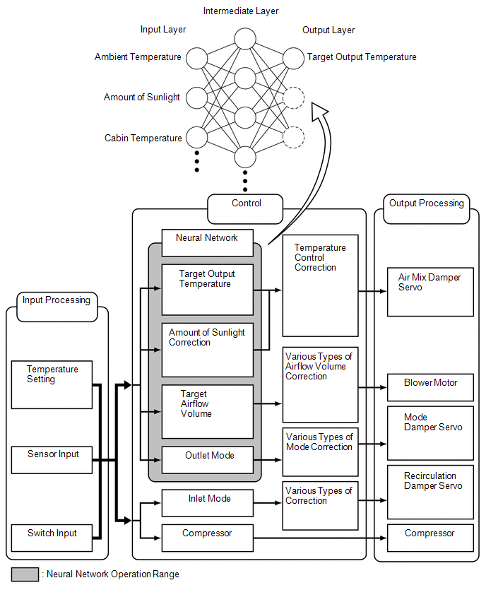
NEURAL NETWORK CONTROL
-
In previous automatic air conditioning systems, the air conditioning amplifier assembly determined the required outlet air temperature and blower air volume in accordance with the calculation formula that has been obtained based on information received from the sensors.
However, because the senses of a person are rather complex, a given temperature is sensed differently, depending on the environment in which the person is situated. For example, a given amount of solar radiation can feel comfortably warm in a cold climate, or extremely uncomfortable in a hot climate. Therefore, as a technique for effecting a higher level of control, a neural network has been adopted in the automatic air conditioning system. With this technique, the data that has been collected under varying environmental conditions is stored in the air conditioning amplifier assembly. The air conditioning amplifier assembly can then effect control to provide enhanced air conditioning comfort.
- The neural network control consists of neurons in the input layer, intermediate layer and output layer. The input layer neurons process the input data of the outside temperature, the amount of sunlight and the room temperature based on the outputs of the switches and sensors, and output them to the intermediate layer neurons. Based on this data, the intermediate layer neurons adjust the strength of the links among the neurons. The sum of these is then calculated by the output layer neurons in the form of the required outlet temperature, solar correction, target airflow volume and outlet mode control volume. Accordingly, the air conditioning amplifier assembly controls the servo motors and blower motor in accordance with the control volumes that have been calculated by the neural network control.
MODE POSITION AND DAMPER OPERATION
Mode Position and Damper Operation.
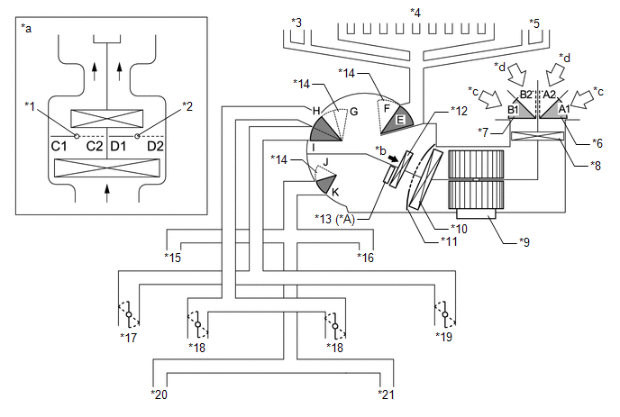
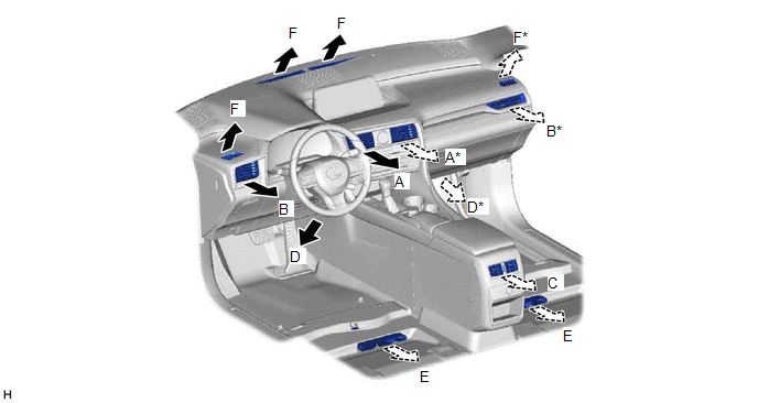
(a) Front Air Conditioning System
| *A | w/ PTC Heater | - | - |
| *1 | Driver Side Air Mix Control Damper | *2 | Front Passenger Side Air Mix Control Damper |
| *3 | Driver Side Side Defroster | *4 | Front Defroster |
| *5 | Front Passenger Side Side Defroster | *6 | Air Inlet Control Damper (Lower Side) |
| *7 | Air Inlet Control Damper (Upper Side) | *8 | Clean Air Filter |
| *9 | Blower Motor with Fan Sub-assembly | *10 | No. 1 Cooler Evaporator Sub-assembly |
| *11 | Air Mix Control Damper | *12 | Heater Radiator Unit Sub-assembly |
| *13 | PTC Heater (Quick Heater Assembly) | *14 | Mode Switching Damper |
| *15 | Driver Side Footwell Register | *16 | Front Passenger Side Footwell Register |
| *17 | Driver Side Side Register | *18 | Center Register |
| *19 | Front Passenger Side Side Register | *20 | Driver Side Rear Footwell Register |
| *21 | Front Passenger Side Rear Footwell Register | - | - |
| *a | Illustration Image View from [A] | *b | [A] View |
| *c | Recirculated Air | *d | Fresh Air |
| Control Damper | Operation Position | Damper Position | Operation |
|---|---|---|---|
| Air Inlet Control Damper (w/ Smog Ventilation Sensor) | FRESH | A1, B1 | Allows fresh air to enter. |
| RECIRCULATION | A2, B2 | Causes internal air to recirculate. | |
| Air Mix Control Damper | Temperature Setting: 16°C (61°F) to 30°C (86°F) | C1 - C2 | Varies the front passenger side mixture ratio of the fresh air and the recirculation air in order to regulate the temperature continuously from HI to LO. |
| D2 - D1 | Varies the driver side mixture ratio of the fresh air and the recirculation air in order to regulate the temperature continuously from HI to LO. | ||
| Air Outlet Control Damper | DEF  | F, H, K | Defrosts the windshield through the center defroster, side defrosters and side registers. |
| FOOT/DEF  | F, H, J to K | Defrosts the windshield through the center defroster, side defrosters, side registers and rear center register, while air is also blown out from the front and rear footwell register ducts. | |
| FOOT  | E, (E to F)*, H, J | Air blows out of the front and rear footwell register ducts and side registers. In addition, air blows out slightly from the center defroster and side defrosters. | |
| B/L  | E, G to I, J to K | Air blows out of the front and rear center registers, side registers and front and rear footwell register ducts. | |
| FACE  | E, G, K | Air blows out of the front and rear center registers and side registers. |
- *: The automatic air conditioning system is operating.
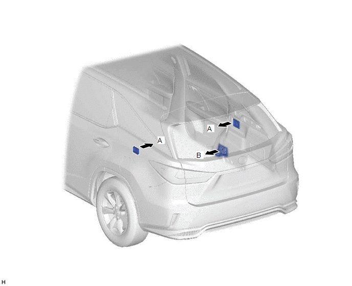
(b) Rear Air Conditioning System
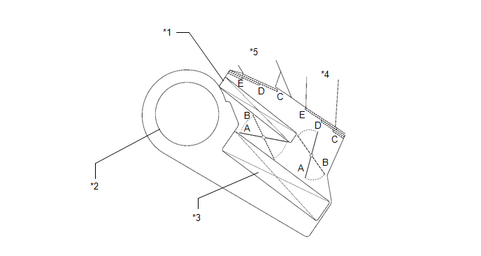
| *1 | Heater Radiator Unit Sub-assembly | *2 | Rear Blower Motor with Fan Sub-assembly |
| *3 | Rear Evaporator Sub-assembly | *4 | Rear Side Register |
| *5 | Rear Footwell Register Duct | - | - |
| Control Damper | Operation Position | Damper Position | Operation |
|---|---|---|---|
| Air Mix Control Damper | MAX COLD to MAX HOT Temperature Setting | A - B | Varies the mixture ratio of the cold air and hot air in order to regulate the temperature continuously between hot and cold. |
| Air Outlet Control Damper | FACE | C | Air blows out of the rear side registers. |
| B/L | D | Air blows out of the rear side registers and rear footwell register ducts. | |
| FOOT | E | Air blows out of the rear footwell register ducts. |
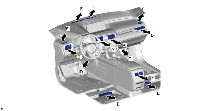
AIR OUTLETS AND AIRFLOW VOLUME
(a) for Front Registers
(1) Air Outlets and Airflow Volume (for All Seat Control Modes).
| Mode | FACE | FOOT | DEF | |||
|---|---|---|---|---|---|---|
| Center | Side | Rear | Front | Rear | F | |
| A | B | C | D | E | ||
| FACE |  | | |  | | |
| B/L |  | | | | | |
| FOOT | |  | | | | |
| FOOT/DEF | |  | | | |  |
| DEF | | | | | | |
The size of each circle ○ indicates the ratio of airflow volume.
(2) Air Outlet and Airflow Volume (for Front Seat Control Modes).
| Mode | FACE | FOOT | DEF | |||
|---|---|---|---|---|---|---|
| Center | Side | Rear | Front | Rear | F | |
| A | B | C | D | E | ||
| FACE | | | | | | |
| B/L | | | | | | |
| FOOT | | | | | | |
| FOOT/DEF | | | | | | |
| DEF | | | | | | |
- *: Airflow is stopped when the front passenger seat is not occupied.
The size of each circle ○ indicates the ratio of airflow volume.
(b) for Rear Registers
| Mode | FACE | FOOT |
|---|---|---|
| A | B | |
| FACE | | |
| B/L | | |
| FOOT | | |
The size of each circle ○ indicates the ratio of airflow volume.
AIR CONDITIONING FUNCTION (for Lexus Enform Remote Compatible Type)
When the engine is started by the remote engine start function, the air conditioning system will operate according to the ambient temperature and customize settings.
| Ambient Temperature | Air Conditioning Control | Defroster/Rear Defogger Control |
|---|---|---|
| 4°C (39.2°F) or less | Operates at set temperature when engine switch turned off*1, *2 | ON |
| Between 5°C (41°F) and 29°C (84.2°F) | Operates at set temperature when engine switch turned off*1 | OFF |
| 30°C (86°F) or more | Operates at set temperature when engine switch turned off*1, *2 | OFF |
- *1: The set temperature can be changed using the application.
- *2: If the A/C switch was off when the engine switch was turned off, the air conditioning system will automatically operate at a set temperature of 25°C (77°F).
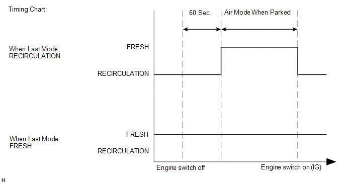
PARKING FRESH CONTROL
When 60 seconds have elapsed since the engine switch has been turned off, the air conditioning amplifier assembly uses control logic which automatically changes the air inlet to FRESH mode to purge undesired odors from the air conditioning unit.
This logic will therefore reduce undesired odors upon starting the air conditioning system.
COMPRESSOR
(a) General:
(1) The compressor is a continuously variable capacity type in which its capacity can be varied in accordance with the cooling load of the air conditioning system.
(2) The compressor consists of a pulley, shaft, lug plate, swash plate, piston, shoe, crank chamber, cylinder, solenoid valve with built-in crank chamber to suction passage (CS) valve, oil separator and variable suction side throttle.
(3) The cooler compressor assembly has an A/C lock sensor that detects whether the compressor is locked.
(4) A solenoid valve is provided to enable the suction pressure to be controlled as desired.
(5) The crank chamber to suction passage (CS) valve, built into the solenoid valve, operates in accordance with the suction pressure.
(6) The oil separator is installed in the refrigerant passage to separate compressor oil from the refrigerant that is discharged. This helps to prevent the compressor oil from flowing into the air conditioning system and reducing cooling effectiveness.
(b) Solenoid Valve Operation:
(1) The crank chamber is connected to the suction passage. A solenoid valve is provided between the suction passage (low pressure) and the discharge passage (high pressure).
(2) The solenoid valve operates under duty cycle control in accordance with the signals from the air conditioning amplifier assembly.
(3) When the solenoid valve closes (solenoid coil is energized), a difference in pressure is created and the pressure in the crank chamber decreases. Then, the pressure that is applied to the right side of the piston becomes greater than the pressure that is applied to the left side of the piston. This compresses the spring and tilts the swash plate. As a result, the piston stroke increases and the discharge capacity also increases.
(4) When the solenoid valve opens (solenoid coil is not energized), the difference in pressure disappears. Then, the pressure that is applied to the left side of the piston becomes the same as the pressure that is applied to the right side of the piston. Thus, the spring elongates and eliminates the tilt of the swash plate. As a result, there is no piston stroke, and the discharge capacity is reduced.
(c) CS Valve Operation:
(1) The CS valve consists of passage A and passage B. If the vehicle is left parked for a long period, refrigerant may accumulate in the crank chamber due to the heat capacity difference.
(2) The solenoid control valve is controlled by the air conditioning amplifier assembly. While the compressor is operating, the solenoid control valve pushes down the CS valve rod and opens passage A.
(3) Under the above condition, only if the refrigerant accumulates in the crank chamber, the crank chamber pressure will become high. As a result, the bellows will contract because of the pressure difference with its internal pressure (vacuum), and opens passage B.
(4) This causes the accumulated refrigerant to be drawn in via passage A and passage B, clearing the accumulated refrigerant earlier and ensuring a more immediate cooling effect.
A/C LOCK SENSOR
The A/C lock sensor sends A/C pulley speed signals to the air conditioning amplifier assembly. The air conditioning amplifier assembly determines whether the A/C compressor is locked or not by using those signals and engine speed signals.
AUTOMATIC RECIRCULATION CONTROL (w/ Smog Ventilation Sensor)
(a) When automatic recirculation control is operating, the air conditioning amplifier assembly automatically changes the air inlet mode to recirculation or fresh mode based on signals from the smog ventilation sensor, cooler (ambient temp. sensor) thermistor and cooler (room temp. sensor) thermistor when AUTO air inlet mode is selected.
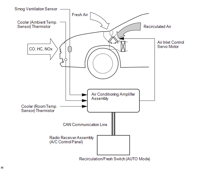
(1) The air conditioning amplifier assembly detects harmful elements (CO, HC and NOx) in the air based on a smog ventilation sensor signal and automatically switches the air inlet mode to recirculation mode to prevent such harmful elements (CO, HC and NOx) from entering the cabin.
(2) The air conditioning amplifier assembly detects cabin temperature based on a room temperature sensor signal and automatically switches the air inlet mode to recirculation mode to prevent the cabin temperature from becoming too high.
(3) The air conditioning amplifier assembly detects the outside temperature based on an ambient temperature sensor signal and automatically switches the air inlet mode to fresh mode to prevent the windshield from fogging up.
NOTICE:
The smog ventilation sensor cannot detect elements such as the smoke from a bonfire or factory exhaust, foul or animal odors, and dirt or dust particles. Therefore, the air inlet mode is not switched automatically in accordance with those elements.
NO. 1 COOLER THERMISTOR
The No. 1 cooler thermistor detects the temperature of the cool air immediately after the evaporator in the form of resistance changes, and outputs it to the air conditioning amplifier assembly.
BLOWER MOTOR WITH FAN SUB-ASSEMBLY
The blower motor has a built-in blower controller, and is controlled using duty control performed by the air conditioning amplifier assembly.
BUS CONNECTOR (AIR CONDITIONING HARNESS ASSEMBLY)
(a) Bus connectors are used in the wire harness that connects the servo motors to the air conditioning amplifier assembly.
(1) Front Air Conditioning System
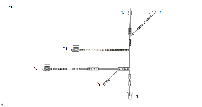
| *a | Example | *b | Bus Connector (to No. 1 Air Conditioning Radiator Damper Servo Sub-assembly) |
| *c | Bus Connector (to No. 3 Air Conditioning Radiator Damper Servo Sub-assembly) | *d | Bus Connector (to No. 2 Air Conditioning Radiator Damper Servo Sub-assembly) |
| *e | Bus Connector (to No. 1 Blower Damper Servo Sub-assembly) | *f | to Air Conditioning Amplifier Assembly |
| *g | to No. 1 Cooler Thermistor | - | - |
(2) Rear Air Conditioning System
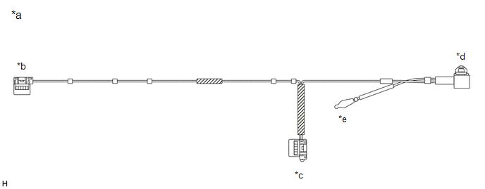
| *a | Example | *b | Bus Connector (to Rear No. 1 Cooling Unit Damper Servo Sub-assembly) |
| *c | Bus Connector (to Rear No. 2 Cooling Unit Damper Servo Sub-assembly) | *d | to Air Conditioning Amplifier Assembly |
| *e | Rear Evaporator Temperature Sensor | - | - |
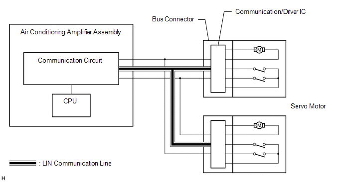
(b) Each bus connector has a built-in communication/driver IC which communicates with the air conditioning amplifier assembly, actuates the servo motor, and has a position detection function. This enables bus communication for the servo motor wire harness, for a more lightweight construction and a reduced number of wires.
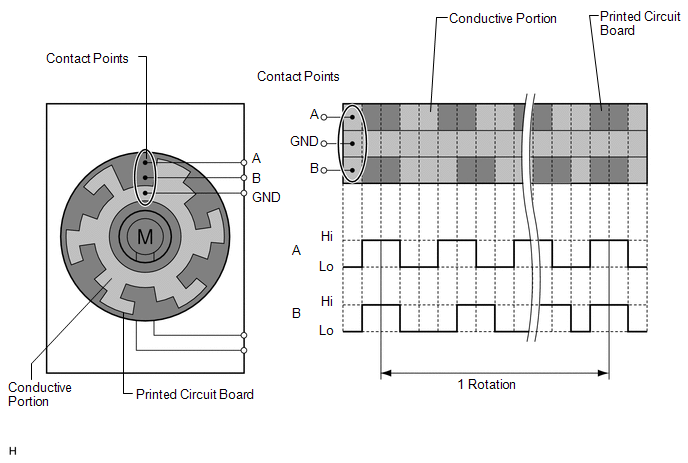
SERVO MOTOR
A pulse pattern type servo motor consists of a printed circuit board and a servo motor. The printed circuit board has three contact points, and can transmit two ON-OFF signals to the air conditioning amplifier assembly based on the difference of the pulse phases. The bus connector can detect the damper position and movement direction with these signals.
QUICK HEATER ASSEMBLY (w/ PTC Heater)
(a) General
(1) The quick heater assembly is located above the heater core in the air conditioning radiator assembly.
(2) The quick heater assembly consists of a PTC element, aluminum fins, and brass plates. When current is applied to the PTC element, it generates heat to warm the air that passes through the unit.
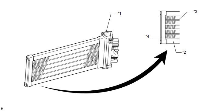
| *1 | Quick Heater Assembly | *2 | Brass Plate |
| *3 | PTC Element | *4 | Aluminum Fin |
(b) Quick Heater Assembly Operating Conditions
(1) The quick heater assembly is turned on and off by the air conditioning amplifier assembly in accordance with the engine coolant temperature, ambient temperature, temperature setting, and electrical load (generator power ratio).
ECO MODE CONTROL
Under the control of ECO mode, the air conditioning amplifier assembly restricts the air conditioning system performance under specified conditions, thus improving fuel economy.
COOLER (ROOM TEMP. SENSOR) THERMISTOR
The cooler (room temp. sensor) thermistor detects the cabin temperature based on changes in the resistance of its built-in thermistor and sends a signal to the air conditioning amplifier assembly.
COOLER (AMBIENT TEMP. SENSOR) THERMISTOR
The cooler (ambient temp. sensor) thermistor detects the outside temperature based on changes in the resistance of its built-in thermistor and sends a signal to the air conditioning amplifier assembly.
AUTOMATIC LIGHT CONTROL SENSOR
The automatic light control sensor detects (in the form of changes in the current that flows through the built-in photo diode) the changes in the amount of sunlight and outputs these sunlight strength signals to the air conditioning amplifier assembly.
AIR CONDITIONER PRESSURE SENSOR
The air conditioner pressure sensor detects the refrigerant pressure and outputs it to the air conditioning amplifier assembly in the form of voltage changes.
COOLER (NO. 2 ROOM TEMP. SENSOR) THERMISTOR (w/ Rear Air Conditioning System)
The cooler (No. 2 room temp. sensor) thermistor detects the rear cabin temperature based on changes in the resistance of its built-in thermistor and sends a signal to the air conditioning amplifier assembly.
 System Diagram
SYSTEM DIAGRAM FRONT AIR CONDITIONING SYSTEM REAR AIR CONDITIONING SYSTEM (w/ Rear Air Conditioning System) Communication Table Sender Receiver Signal Communication Line Air condi ...
 Customize Parameters
CUSTOMIZE PARAMETERS CUSTOMIZE AIR CONDITIONING SYSTEM (a) Customizing with the Techstream. NOTICE:
When the customer requests a change in a function, first make sure that the function can be custo ...
Other materials:
Lexus RX (RX 350L, RX450h) 2016-2026 Repair Manual > Steering Pad Switch: Components
COMPONENTS ILLUSTRATION *1 STEERING PAD SWITCH ASSEMBLY - - N*m (kgf*cm, ft.*lbf): Specified torque - - ...
Lexus RX (RX 350L, RX450h) 2016-2026 Repair Manual > Air Conditioning System: Air Mix Damper Control Servo Motor Circuit (Passenger Side) (B1441/41)
DESCRIPTION The No. 1 air conditioning radiator damper servo sub-assembly (front passenger side air mix) sends pulse signals to inform the air conditioning amplifier assembly of the damper position. The air conditioning amplifier assembly activates the motor (normal or reverse) based on these signal ...
Lexus RX (RX 350L, RX450h) 2016-{YEAR} Owners Manual
- For your information
- Pictorial index
- For safety and security
- Instrument cluster
- Operation of each component
- Driving
- Lexus Display Audio system
- Interior features
- Maintenance and care
- When trouble arises
- Vehicle specifications
- For owners
Lexus RX (RX 350L, RX450h) 2016-{YEAR} Repair Manual

0.0141