Lexus RX (RX 350L, RX450h) 2016-2026 Repair Manual: System Diagram
SYSTEM DIAGRAM
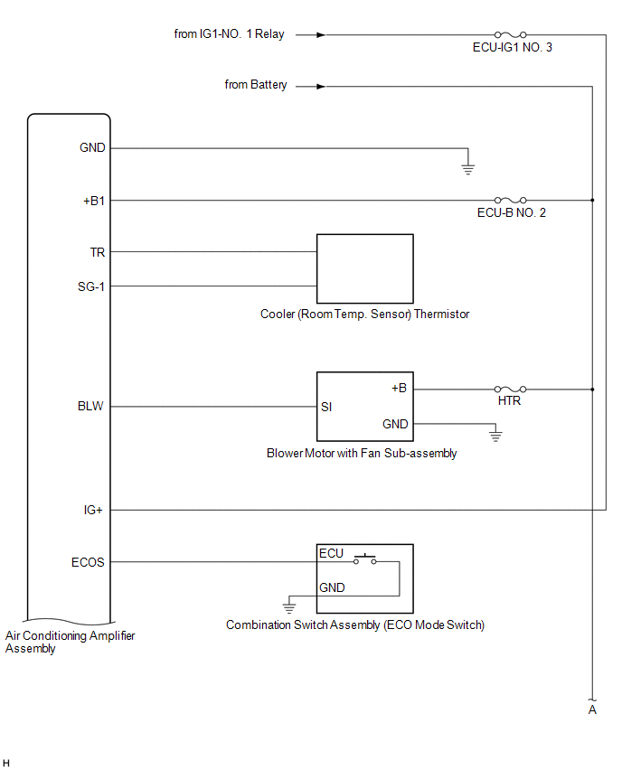
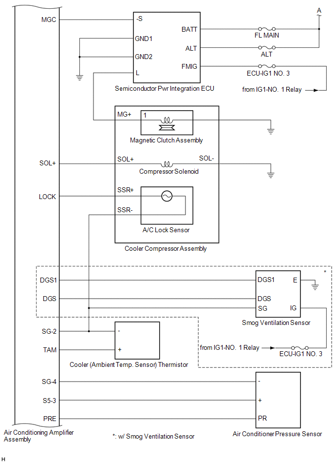
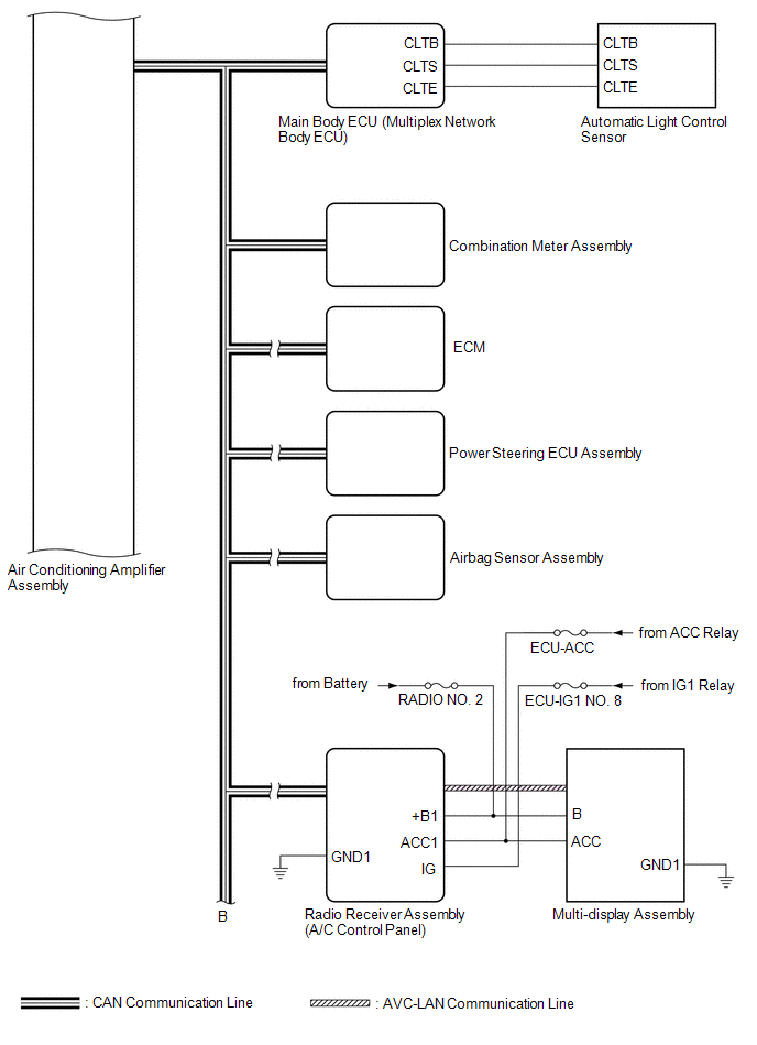
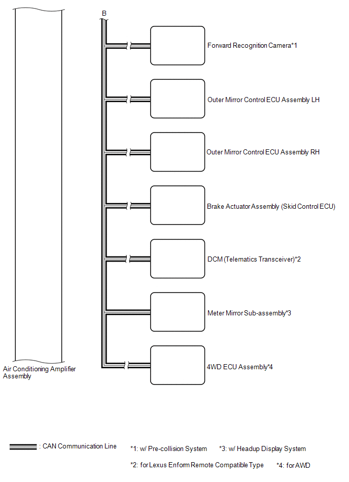
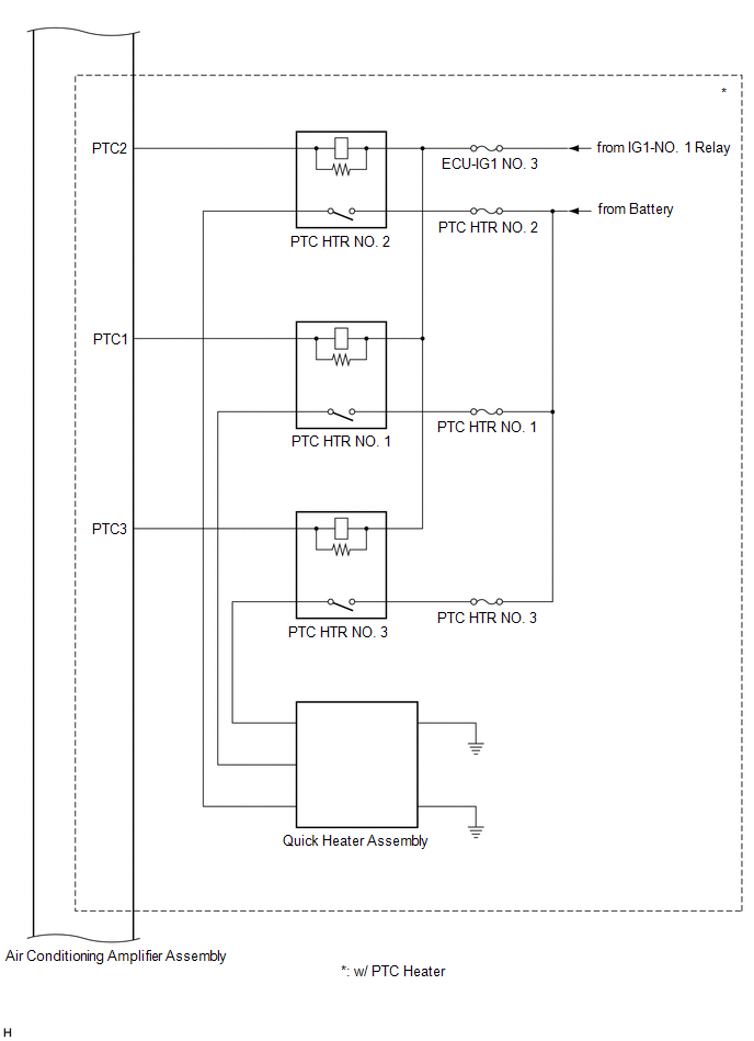
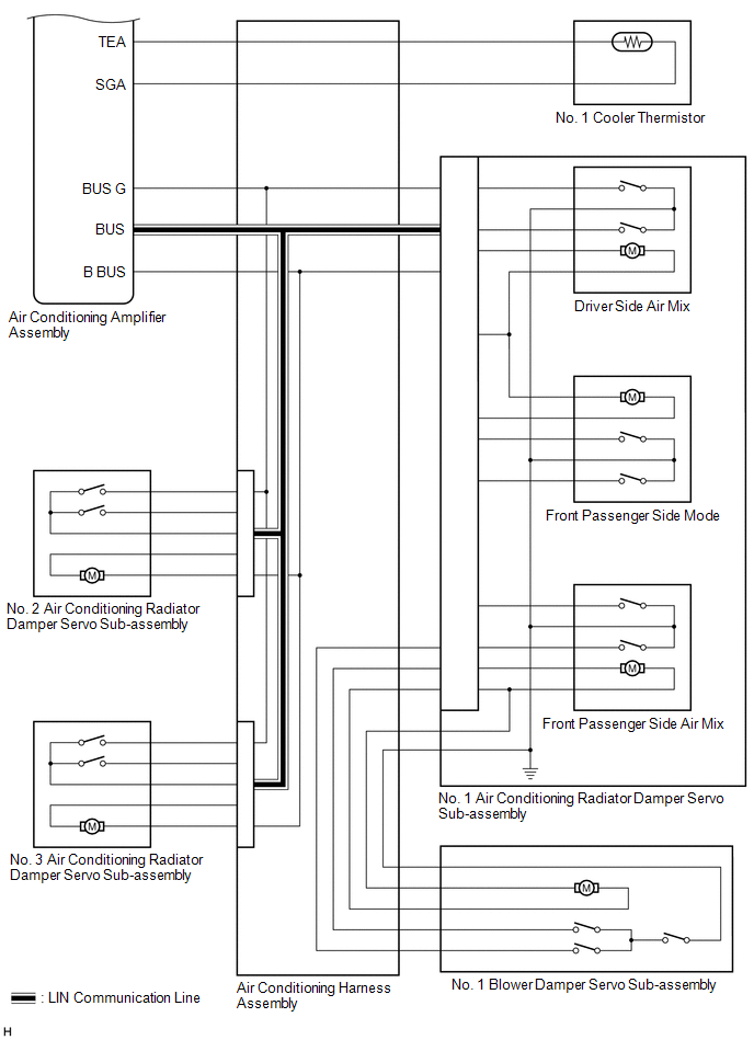
FRONT AIR CONDITIONING SYSTEM
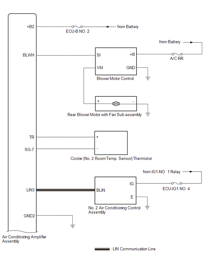
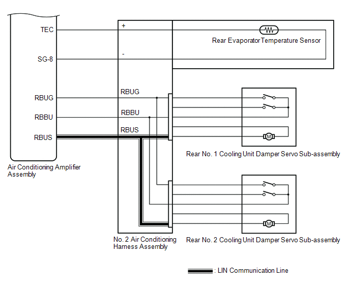
REAR AIR CONDITIONING SYSTEM (w/ Rear Air Conditioning System)
 Communication Table
 | Sender | Receiver | Signal | Communication Line |
|---|---|---|---|
| Air conditioning amplifier assembly | ECM | Magnetic clutch request signal | CAN |
| Idle up request signal | |||
| Heater idle up request signal | |||
| ECO mode switch information signal | |||
| Super cooling control state signal | |||
| Charging control inhibit signal | |||
| Motor cooling fan drive request signal | |||
| Prior A/C control request signal | |||
| Acceleration cut inhibit signal | |||
| PTC heater control request signal | |||
| Generator control inhibit signal | |||
| Transmission system cooling performance assistance request signal | |||
| Request control by refrigerant signal | |||
| Transmission system heating performance assistance request signal | |||
| Ambient temperature before correction signal | |||
| Refrigerant information signal | |||
| Evaporator temperature sensor signal | |||
| Variable compressor solenoid current signal | |||
| Air conditioner pressure sensor signal | |||
| Rear defogger drive request signal | |||
| Ambient temperature display signal | |||
| Air conditioning amplifier assembly | Radio receiver assembly (A/C control panel) | A/C display request signal | CAN |
| AUTO indicator signal | |||
| Front defroster indicator signal | |||
| Rear defogger indicator signal | |||
| Inlet auto indicator signal | |||
| Recirculation indicator signal | |||
| Fresh indicator signal | |||
| A/C indicator signal | |||
| Wiper deicer indicator signal | |||
| DUAL indicator signal | |||
| Blower level indicator signal | |||
| Outlet auto indicator signal | |||
| Outlet indicator signal | |||
| Blower manual status signal | |||
| S-FLOW switch indicator signal | |||
| Blower customize indicator signal | |||
| A/C on-screen request signal | |||
| S-FLOW state signal | |||
| Driver side temperature display signal | |||
| Front passenger side temperature display signal | |||
| A/C eco state indicator signal | |||
| A/C screen select information signal | |||
| DUAL switch design select information signal | |||
| Temperature unit select information signal | |||
| Blower step select information signal | |||
| Speech recognition level information signal | |||
| Switch select information signal | |||
| Destination select information signal | |||
| Control information signal | |||
| A/C recirculation/fresh collaborated with navi information signal | |||
| Rear defogger drive request signal | |||
| Mirror heater drive request signal | |||
| In-vehicle temperature signal | |||
| Ambient temperature display signal | |||
| Ambient temperature display whole number/decimal (0/0.5°C) signal | |||
| RearR AUTO indicator signal*5 | |||
| Rear blower manual status signal*5 | |||
| Rear blower customize indicator signal*5 | |||
| Rear blower level indicator signal*5 | |||
| Rear AUTO indicator signal*5 | |||
| RearR side or Rear side temperature display signal*5 | |||
| Air conditioning amplifier assembly | Combination meter assembly | Ambient temperature display signal | CAN |
| Ambient temperature display whole number/decimal (0/0.5°C) signal | |||
| A/C load limitation warning signal | |||
| Air conditioning amplifier assembly | Main body ECU (multiplex network body ECU) | Ambient temperature display signal | CAN |
| Air conditioning amplifier assembly | Meter mirror sub-assembly*1 | Ambient temperature signal | CAN |
| Ambient temperature display whole number/decimal (0/0.5°C) signal | |||
| Air conditioning amplifier assembly | Outer mirror control ECU assembly LH | Mirror heater drive request signal | CAN |
| Air conditioning amplifier assembly | Outer mirror control ECU assembly RH | Mirror heater drive request signal | CAN |
| Air conditioning amplifier assembly | 4WD ECU assembly*2 | Ambient temperature signal | CAN |
| Air conditioning amplifier assembly | Brake actuator assembly (skid control ECU) | Ambient temperature before correction signal | CAN |
| In-vehicle temperature signal | |||
| Ambient temperature display signal | |||
| Air conditioning amplifier assembly | Forward recognition camera*3 | Ambient temperature display signal | CAN |
| Air conditioning amplifier assembly | DCM (telematics transceiver)*4 | Drive recorder signal | CAN |
| Front defroster indicator signal | |||
| A/C indicator signal | |||
| S-FLOW switch indicator signal | |||
| Driver side temperature display signal | |||
| In-vehicle temperature signal | |||
| Ambient temperature display signal | |||
| A/C control state signal | |||
| ECM | Air conditioning amplifier assembly | ECO mode indicator signal | CAN |
| Drive mode select signal | |||
| Engine type information signal | |||
| Engine speed data signal | |||
| Alternative field duty value signal | |||
| Engine coolant temperature signal | |||
| A/C control cut-off signal | |||
| Variable control inhibition signal | |||
| Number of PTC heaters which are permitted signal | |||
| Compulsory internal air circulation at high coolant temperature command signal | |||
| Radio receiver assembly (A/C control panel) | Air conditioning amplifier assembly | Tunnel signal | CAN |
| AVN1S04 valid information signal | |||
| A/C ECO switch status signal | |||
| Blower customize switch state signal | |||
| Panel design information signal | |||
| Gas auto LED select information signal | |||
| AUTO switch state signal | |||
| Front defroster switch state signal | |||
| Rear defogger switch state signal | |||
| Air inlet switch state signal | |||
| OFF switch state signal | |||
| A/C switch state signal | |||
| Wiper deicer switch signal | |||
| DUAL switch state signal | |||
| Mode switch state signal | |||
| Blower up switch state signal | |||
| Blower down switch state signal | |||
| Air outlet switch state signal | |||
| Driver side TEMP up switch state signal | |||
| Driver side TEMP down switch state signal | |||
| Front passenger side TEMP up switch state signal | |||
| Front passenger side TEMP down switch state signal | |||
| Air inlet fresh switch state signal | |||
| Air inlet recirculation switch state signal | |||
| Switch state that shows concentration on one seat signal | |||
| Gas reception setting screen signal | |||
| Gas reception setting switch state signal | |||
| Blower front level 7 switch state signal | |||
| Blower front level 6 switch state signal | |||
| Blower front level 5 switch state signal | |||
| Blower front level 4 switch state signal | |||
| Blower front level 3 switch state signal | |||
| Blower front level 2 switch state signal | |||
| Blower front level 1 switch state signal | |||
| A/C-navi cooperation state signal | |||
| Rear side seat speech recognition mode information signal | |||
| Rear side seat speech recognition date addition subtraction information signal | |||
| Rear side seat speech recognition temperature directions data signal | |||
| Driver side seat speech recognition mode information signal | |||
| Driver side seat speech recognition date addition subtraction information signal | |||
| Driver side seat speech recognition temperature directions data signal | |||
| Front passenger side seat speech recognition mode information signal | |||
| Front passenger side seat speech recognition date addition subtraction information signal | |||
| Front passenger side seat speech recognition temperature directions data signal | |||
| Sensor fail signal | |||
| Confidence MMC signal | |||
| Confidence direction signal | |||
| Switch state of A/C signal | |||
| AVN1S39 valid information signal | |||
| RearR AUTO switch state signal*5 | |||
| Rear blower up switch state signal*5 | |||
| Rear blower down switch state signal*5 | |||
| RearR TEMP up switch state signal*5 | |||
| RearR TEMP down switch state signal*5 | |||
| RearR air outlet switch state signal*5 | |||
| RearR mode switch state signal*5 | |||
| Rear OFF switch state signal*5 | |||
| Rear control inhibit switch state signal*5 | |||
| Rear AUTO switch state signal*5 | |||
| Blower rear level 7 switch state signal*5 | |||
| Blower rear level 6 switch state signal*5 | |||
| Blower rear level 5 switch state signal*5 | |||
| Blower rear level 4 switch state signal*5 | |||
| Blower rear level 3 switch state signal*5 | |||
| Blower rear level 2 switch state signal*5 | |||
| Blower rear level 1 switch state signal*5 | |||
| Main body ECU (multiplex network body ECU) | Air conditioning amplifier assembly | Auto dimmer signal | CAN |
| Rear right side courtesy switch signal | |||
| Rear left side courtesy switch signal | |||
| High beam headlight request signal | |||
| Low beam headlight request signal | |||
| Destination symbol signal | |||
| Destination package signal | |||
| Steering wheel signal | |||
| Wiper deicer signal | |||
| Main body request signal | |||
| Solar data (R) signal | |||
| Solar data (L) signal | |||
| Combination meter assembly | Air conditioning amplifier assembly | Vehicle speed signal (meter to other) | CAN |
| Front passenger side seat occupant status signal | |||
| Power steering ECU assembly | Air conditioning amplifier assembly | Loading control level signal | CAN |
| Airbag sensor assembly | Air conditioning amplifier assembly | Front passenger side seat occupant status signal | CAN |
| DCM (telematics transceiver)*4 | Air conditioning amplifier assembly | Remote engine start system control signal | CAN |
| Defogger control signal | |||
| Air conditioner control signal |
- *1: w/ Headup Display System
- *2: for AWD
- *3: w/ Pre-collision System
- *4: for Lexus Enform Remote Compatible Type
- *5: w/ Rear Air Conditioning System
 Parts Location
PARTS LOCATION ILLUSTRATION *A w/o Rear Air Conditioning System *B w/ PTC Heater *C w/ Smog Ventilation Sensor *D w/ Pre-collision System *1 AIR CONDITIONER PRESSURE SENSOR ...
 System Description
SYSTEM DESCRIPTION GENERAL The air conditioning system has the following controls. Control Outline Neural Network Control This control is capable of performing complex control by artificial ...
Other materials:
Lexus RX (RX 350L, RX450h) 2016-2026 Repair Manual > Can Communication System: Dtc Combination Table
DTC COMBINATION TABLE HOW TO INTERPRET COMMUNICATION DTCS (DTCS THAT START WITH U) (a) If a CAN communication error cannot be reproduced, determine the suspected malfunctioning part using the DTCs stored in ECUs that are connected to the CAN buses by following the procedure below. HINT: Communicatio ...
Lexus RX (RX 350L, RX450h) 2016-2026 Repair Manual > Rear Air Conditioning Unit: Reassembly
REASSEMBLY PROCEDURE 1. INSTALL NO. 2 AIR CONDITIONING HARNESS ASSEMBLY (a) Engage the 2 claws to install the No. 2 air conditioning harness assembly. 2. INSTALL REAR EVAPORATOR SUB-ASSEMBLY (a) Install the rear evaporator sub-assembly as shown in the illustration. Install in t ...
Lexus RX (RX 350L, RX450h) 2016-{YEAR} Owners Manual
- For your information
- Pictorial index
- For safety and security
- Instrument cluster
- Operation of each component
- Driving
- Lexus Display Audio system
- Interior features
- Maintenance and care
- When trouble arises
- Vehicle specifications
- For owners
Lexus RX (RX 350L, RX450h) 2016-{YEAR} Repair Manual

0.0131