Lexus RX (RX 350L, RX450h) 2016-2026 Repair Manual: Camshaft Position "B" - Actuator Bank 1 Circuit Open (P001313,P002313)
DESCRIPTION
The Variable Valve Timing (VVT) system adjusts the exhaust valve timing to improve driveability. The engine oil pressure turns the VVT controller to adjust the valve timing.
The cam timing oil control solenoid assembly operates according to signals received from the ECM to control the position of the camshaft timing oil control valve assembly and supply engine oil. The camshaft timing oil control valve assembly moves when the ECM applies 12 V to the cam timing oil control solenoid assembly. The ECM changes the energizing time of the cam timing oil control solenoid assembly (duty-cycle)in accordance with the camshaft position, crankshaft position, throttle position, etc.

| DTC No. | Detection Item | DTC Detection Condition | Trouble Area | MIL | Memory | Note |
|---|---|---|---|---|---|---|
| P001313 | Camshaft Position "B" - Actuator Bank 1 Circuit Open | Open or short in cam timing oil control solenoid assembly (for exhaust camshaft of bank 1) circuit (1 trip detection logic). |
| Comes on | DTC stored | SAE Code: P0013 |
| P002313 | Camshaft Position "B" - Actuator Bank 2 Circuit Open | Open or short in cam timing oil control solenoid assembly (for exhaust camshaft of bank 2) circuit (1 trip detection logic). |
| Comes on | DTC stored | SAE Code: P0023 |
MONITOR DESCRIPTION
This DTC is designed to detect an open or short in the cam timing oil control solenoid assembly (for exhaust camshaft) circuit. If the cam timing oil control solenoid duty-cycle is excessively high or low while the engine switch is on (IG) or the engine is running, the ECM will illuminate the MIL and store this DTC.
MONITOR STRATEGY
| Related DTCs | P0013: Cam timing oil control solenoid assembly (for exhaust camshaft of bank 1) range check P0023: Cam timing oil control solenoid assembly (for exhaust camshaft of bank 2) range check |
| Required Sensors/Components (Main) | Cam timing oil control solenoid assembly (for exhaust camshaft) |
| Required Sensors/Components (Related) | - |
| Frequency of Operation | Continuous |
| Duration | 1 second |
| MIL Operation | Immediate |
| Sequence of Operation | None |
TYPICAL ENABLING CONDITIONS
All| Monitor runs whenever the following DTCs are not stored | None |
| All of the following conditions are met | - |
| Battery voltage | 8 V or higher |
| Starter | Off |
| Engine switch | On (IG) |
| Time after engine switch off to on (IG) | 0.5 seconds or more |
| Either of the following conditions is met | A or B |
| A. Both of the following conditions are met | - |
| Battery voltage | 11 V or higher, and less than 13 V |
| Target duty cycle | Less than 70% |
| B. Both of the following conditions are met | - |
| Battery voltage | 13 V or higher |
| Target duty cycle | Less than 80% |
| Both of the following conditions are met | - |
| Current cut status | Not cut |
| Target duty cycle | 25% or higher |
TYPICAL MALFUNCTION THRESHOLDS
Case 1| Output duty cycle | 100% or higher |
| Output duty cycle | 0% or less |
CONFIRMATION DRIVING PATTERN
HINT:
-
After repair has been completed, clear the DTC and then check that the vehicle has returned to normal by performing the following All Readiness check procedure.
Click here

-
When clearing the permanent DTCs, refer to the "CLEAR PERMANENT DTC" procedure.
Click here
- Connect the Techstream to the DLC3.
- Turn the engine switch on (IG).
- Turn the Techstream on.
- Clear the DTCs (even if no DTCs are stored, perform the clear DTC procedure).
- Turn the engine switch off and wait for at least 30 seconds.
- Start the engine [A].
- Wait 5 seconds or more [B].
- Turn the Techstream on.
- Enter the following menus: Powertrain / Engine / Trouble Codes [C].
-
Read the pending DTCs.
HINT:
- If a pending DTC is output, the system is malfunctioning.
- If a pending DTC is not output, perform the following procedure.
- Enter the following menus: Powertrain / Engine / Utility / All Readiness.
- Input the DTC: P001313 or P002313.
-
Check the DTC judgment result.
Techstream Display
Description
NORMAL
- DTC judgment completed
- System normal
ABNORMAL
- DTC judgment completed
- System abnormal
INCOMPLETE
- DTC judgment not completed
- Perform driving pattern after confirming DTC enabling conditions
HINT:
- If the judgment result is NORMAL, the system is normal.
- If the judgment result is ABNORMAL, the system has a malfunction.
- If the judgment result is INCOMPLETE, perform steps [A] through [C] again.
-
[A] to [C]: Normal judgment procedure.
The normal judgment procedure is used to complete DTC judgment and also used when clearing permanent DTCs.
- When clearing the permanent DTCs, do not disconnect the cable from the battery terminal or attempt to clear the DTCs during this procedure, as doing so will clear the universal trip and normal judgment histories.
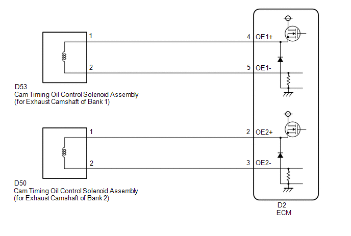
WIRING DIAGRAM
CAUTION / NOTICE / HINT
HINT:
- If DTC P001313 is output, check the VVT system (for exhaust camshaft of bank 1) circuit.
- If DTC P002313 is output, check the VVT system (for exhaust camshaft of bank 2) circuit.
-
Bank 1 refers to the bank that includes the No. 1 cylinder*.
*: The No. 1 cylinder is the cylinder which is farthest from the transaxle.
- Bank 2 refers to the bank that does not include the No. 1 cylinder.
- Read freeze frame data using the Techstream. The ECM records vehicle and driving condition information as freeze frame data the moment a DTC is stored. When troubleshooting, freeze frame data can help determine if the vehicle was moving or stationary, if the engine was warmed up or not, if the air fuel ratio was lean or rich, and other data from the time the malfunction occurred.
PROCEDURE
| 1. | READ OUTPUT DTC (DTC P001313 OR P002313) |
(a) Connect the Techstream to the DLC3.
(b) Turn the engine switch on (IG).
(c) Turn the Techstream on.
(d) Clear the DTC after recording the freeze frame data and DTC.
Powertrain > Engine > Clear DTCs(e) Turn the engine switch off and wait for at least 30 seconds.
(f) Start the engine.
(g) Turn the Techstream on.
(h) Enter the following menus: Powertrain / Engine / Trouble Codes.
(i) Read the DTCs.
Powertrain > Engine > Trouble Codes| Result | Proceed to |
|---|---|
| DTC P001313 or P002313 is output | A |
| DTCs are not output | B |
| B |  | CHECK FOR INTERMITTENT PROBLEMS |
|
.gif)
| 2. | INSPECT CAM TIMING OIL CONTROL SOLENOID ASSEMBLY (FOR EXHAUST CAMSHAFT) |
(a) Inspect the cam timing oil control solenoid assembly (for exhaust camshaft).
-
for Bank 1: Click here
-
for Bank 2: Click here
| NG | | REPLACE CAM TIMING OIL CONTROL SOLENOID ASSEMBLY (FOR EXHAUST CAMSHAFT) |
|
| 3. | CHECK HARNESS AND CONNECTOR (CAM TIMING OIL CONTROL SOLENOID ASSEMBLY (FOR EXHAUST CAMSHAFT) - ECM) |
(a) Disconnect the cam timing oil control solenoid assembly (for exhaust camshaft) connector.
(b) Disconnect the ECM connector.
(c) Measure the resistance according to the value(s) in the table below.
Standard Resistance:
| Tester Connection | Condition | Specified Condition |
|---|---|---|
| D53-1 - D2-4 (OE1+) | Always | Below 1 Ω |
| D53-2 - D2-5 (OE1-) | Always | Below 1 Ω |
| D50-1 - D2-2 (OE2+) | Always | Below 1 Ω |
| D50-2 - D2-3 (OE2-) | Always | Below 1 Ω |
| D53-1 or D2-4 (OE1+) - Body ground and other terminals | Always | 10 kΩ or higher |
| D53-2 or D2-5 (OE1-) - Body ground and other terminals | Always | 10 kΩ or higher |
| D50-1 or D2-2 (OE2+) - Body ground and other terminals | Always | 10 kΩ or higher |
| D50-2 or D2-3 (OE2-) - Body ground and other terminals | Always | 10 kΩ or higher |
| OK | | REPLACE ECM |
| NG | | REPAIR OR REPLACE HARNESS OR CONNECTOR |
 Camshaft Position "A" - Timing Over-Advanced or System Performance Bank 1 Mechanical Failure (P001107,P002107)
DESCRIPTION Refer to DTC P001013. Click here DTC No. Detection Item DTC Detection Condition Trouble Area MIL Memory Note P001107 Camshaft Position "A" - Timing Over-Advanced or ...
 Camshaft Position "B" - Timing Over-Advanced or System Performance Bank 1 (P001400,P001500,P002400,P002500)
DESCRIPTION Refer to DTC P001313. Click here DTC No. Detection Item DTC Detection Condition Trouble Area MIL Memory Note P001400 Camshaft Position "B" - Timing Over-Advanced or ...
Other materials:
Lexus RX (RX 350L, RX450h) 2016-2026 Repair Manual > Sfi System: Actuator Supply Voltage "A" Circuit Short to Ground or Open (P065714)
DESCRIPTION The electronic throttle control system has a dedicated power supply circuit. The voltage (+BM) is monitored and when it is low (less than 4 V), the ECM determines that there is a malfunction in the electronic throttle control system and cuts off the current to the throttle actuator. When ...
Lexus RX (RX 350L, RX450h) 2016-2026 Repair Manual > Rear No. 2 Seat Outer Belt Assembly: Components
COMPONENTS ILLUSTRATION *A for RH Side *B for LH Side *1 FRONT DECK SIDE TRIM COVER *2 REAR DOOR INSIDE SCUFF PLATE *3 REAR DOOR SCUFF PLATE *4 REAR SEAT OUTER TRACK BRACKET COVER LH *5 REAR SEAT OUTER TRACK BRACKET COVER RH *6 REAR SEAT SIDE GARNISH ILLUST ...
Lexus RX (RX 350L, RX450h) 2016-{YEAR} Owners Manual
- For your information
- Pictorial index
- For safety and security
- Instrument cluster
- Operation of each component
- Driving
- Lexus Display Audio system
- Interior features
- Maintenance and care
- When trouble arises
- Vehicle specifications
- For owners
Lexus RX (RX 350L, RX450h) 2016-{YEAR} Repair Manual

0.0105