Lexus RX (RX 350L, RX450h) 2016-2025 Repair Manual: Crankshaft Position Sensor "A" Circuit Short to Ground (P033511,P033515,P03351F,P03352A,P033531)
DESCRIPTION
The crankshaft position sensor system consists of a crankshaft position sensor plate and Magneto Resistance Element (MRE) type sensor. The crankshaft position sensor plate has 34 teeth at 10° intervals (2 teeth are missing for detecting top dead center), and is installed on the crankshaft. The crankshaft position sensor generates 34 signals per crankshaft revolution. The ECM uses the NE signal to detect the crankshaft position and engine speed.
| DTC No. | Detection Item | DTC Detection Condition | Trouble Area | MIL | Memory | Note |
|---|---|---|---|---|---|---|
| P033511 | Crankshaft Position Sensor "A" Circuit Short to Ground | The crankshaft position sensor output voltage is less than 0.3 V for 4 seconds or more (1 trip detection logic). |
| Comes on | DTC stored | SAE Code: P0337 |
| P033515 | Crankshaft Position Sensor "A" Circuit Short to Battery or Open | The crankshaft position sensor output voltage is higher than 4.7 V for 4 seconds or more (1 trip detection logic). |
| Comes on | DTC stored | SAE Code: P0338 |
| P03351F | Crankshaft Position Sensor "A" Circuit Intermittent | Under conditions (a), (b) and (c), no crankshaft position sensor signal to ECM for 0.05 seconds or more (1 trip detection logic): (a) Engine speed is 1000 rpm or more. (b) Starter signal is off. (c) 3 seconds or more have elapsed since the starter signal switched from on to off. |
| Does not come on | DTC stored | SAE Code: P0339 |
| P03352A | Crankshaft Position Sensor "A" Signal Stuck in Range | No crankshaft position sensor signal to the ECM while cranking (1 trip detection logic). |
| Comes on | DTC stored | SAE Code: P0335 |
| P033531 | Crankshaft Position Sensor "A" No Signal | The engine stalls and the engine speed signal value decreases rapidly (1 trip detection logic). |
| Comes on | DTC stored | SAE Code: P0335 |
-
Reference: Inspection using an oscilloscope.
.png)
HINT:
The correct waveform is as shown.
ECM Terminal Name
Between NE+ and NE-
Tester Range
2 V/DIV., 20 ms./DIV.
Condition
Idling with warm engine
MONITOR DESCRIPTION
A DTC will be stored if any of the following occurs:
- The crankshaft position sensor signal (NE signal) is not received by the ECM when the engine is being cranked.
- The crankshaft position sensor signal (NE signal) is not received by the ECM when the engine is running.
- The engine stalls and the engine speed signal value decreases rapidly (under normal conditions the engine speed will decrease gradually).
- The crankshaft position sensor output voltage is above or below the threshold.
MONITOR STRATEGY
| Related DTCs | P0335: Crankshaft position sensor verify pulse input P0337: Crankshaft position sensor range check (Low voltage) P0338: Crankshaft position sensor range check (High voltage) |
| Required Sensors/Components (Main) | Crankshaft position sensor |
| Required Sensors/Components (Related) | VVT sensor |
| Frequency of Operation | Continuous |
| Duration | 4.7 seconds: P0335 (case 1) -: P0335 (case 2) 4 seconds: P0337, P0338 |
| MIL Operation | Immediate |
| Sequence of Operation | None |
TYPICAL ENABLING CONDITIONS
P0335: Crankshaft Position Sensor Verify Pulse Input (Case 1)| Monitor runs whenever following DTCs not present | None |
| All of the following conditions are met | - |
| Battery voltage | Higher than 6 V |
| Crankshaft position sensor voltage | 0.3 to 4.7 V |
| Starter | On |
| Minimum battery voltage while starter on | Less than 11 V |
| Monitor runs whenever following DTCs not present | None |
| All of the following conditions are met | - |
| Battery voltage | Higher than 6 V |
| Crankshaft position sensor voltage | 0.3 to 4.7 V |
| Starter | Off |
| Engine speed (Top dead center) | 600 rpm or more |
| Engine speed (30°CA) | 600 rpm or more |
| Monitor runs whenever following DTCs not present | None |
| All of the following conditions are met | - |
| Battery voltage | 8 V or higher |
| Engine switch | On (IG) |
| Starter | Off |
TYPICAL MALFUNCTION THRESHOLDS
P0335: Crankshaft Position Sensor Verify Pulse Input (Case 1 and Case 2)| Engine speed signal | No signal |
| Crankshaft position sensor voltage | Less than 0.3 V |
| Crankshaft position sensor voltage | Higher than 4.7 V |
CONFIRMATION DRIVING PATTERN
HINT:
-
After repair has been completed, clear the DTC and then check that the vehicle has returned to normal by performing the following All Readiness check procedure.
Click here
.gif)
-
When clearing the permanent DTCs, refer to the "CLEAR PERMANENT DTC" procedure.
Click here
- Connect the Techstream to the DLC3.
- Turn the engine switch on (IG).
- Turn the Techstream on.
- Clear the DTCs (even if no DTCs are stored, perform the clear DTC procedure).
- Turn the engine switch off and wait for at least 30 seconds.
- Start the engine [A].
- Turn the Techstream on.
- Idle the engine for 20 seconds or more [B].
- Enter the following menus: Powertrain / Engine / Trouble Codes [C].
-
Read the pending DTCs.
HINT:
- If a pending DTC is output, the system is malfunctioning.
- If a pending DTC is not output, perform the following procedure.
- Enter the following menus: Powertrain / Engine / Utility / All Readiness.
- Input the DTC: P033511, P033515, P03351F, P03352A or P033531.
-
Check the DTC judgment result.
Techstream Display
Description
NORMAL
- DTC judgment completed
- System normal
ABNORMAL
- DTC judgment completed
- System abnormal
INCOMPLETE
- DTC judgment not completed
- Perform driving pattern after confirming DTC enabling conditions
HINT:
- If the judgment result is NORMAL, the system is normal.
- If the judgment result is ABNORMAL, the system has a malfunction.
-
[A] to [C]: Normal judgment procedure.
The normal judgment procedure is used to complete DTC judgment and also used when clearing permanent DTCs.
- When clearing the permanent DTCs, do not disconnect the cable from the battery terminal or attempt to clear the DTCs during this procedure, as doing so will clear the universal trip and normal judgment histories.
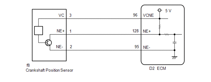
WIRING DIAGRAM
CAUTION / NOTICE / HINT
HINT:
- If no problem is found by this diagnostic troubleshooting procedure, check for problems by referring to the engine mechanical section.
-
The engine speed can be checked by using the Techstream. To perform the check, follow the procedures below:
- Connect the Techstream to the DLC3.
- Start the engine.
- Turn the Techstream on.
- Enter the following menus: Powertrain / Engine / Data List / Engine Speed.
- The engine speed may be indicated as zero despite the engine running normally. This is caused by a lack of NE signals from the crankshaft position sensor. Alternatively, the engine speed may be indicated as lower than the actual engine speed if the crankshaft position sensor output voltage is insufficient.
- Read freeze frame data using the Techstream. The ECM records vehicle and driving condition information as freeze frame data the moment a DTC is stored. When troubleshooting, freeze frame data can help determine if the vehicle was moving or stationary, if the engine was warmed up or not, if the air fuel ratio was lean or rich, and other data from the time the malfunction occurred.
PROCEDURE
| 1. | READ VALUE USING TECHSTREAM (ENGINE SPEED) |
(a) Connect the Techstream to the DLC3.
(b) Turn the engine switch on (IG).
(c) Turn the Techstream on.
(d) Enter the following menus: Powertrain / Engine / Data List / Engine Speed.
Powertrain > Engine > Data List| Tester Display |
|---|
| Engine Speed |
(e) Start the engine.
(f) Read the values displayed on the Techstream while the engine is running.
Standard:
Correct values are displayed.
HINT:
- To check the engine speed change, display the graph on the Techstream.
- If the engine does not start, check the engine speed while cranking.
- If the engine speed indicated on the Techstream remains at zero (0), there may be an open or short in the crankshaft position sensor circuit.
| OK | .gif) | CHECK FOR INTERMITTENT PROBLEMS |
|
.gif)
| 2. | CHECK TERMINAL VOLTAGE (POWER SOURCE OF CRANKSHAFT POSITION SENSOR) |
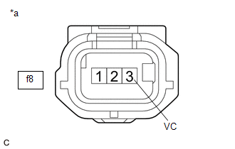
| *a | Front view of wire harness connector (to Crankshaft Position Sensor) |
(a) Disconnect the crankshaft position sensor connector.
(b) Turn the engine switch on (IG).
(c) Measure the voltage according to the value(s) in the table below.
Standard Voltage:
| Tester Connection | Condition | Specified Condition |
|---|---|---|
| f8-3 (VC) - Body ground | Engine switch on (IG) | 4.5 to 5.5 V |
| NG | | GO TO STEP 8 |
|
| 3. | CHECK HARNESS AND CONNECTOR (CRANKSHAFT POSITION SENSOR - ECM) |
(a) Disconnect the crankshaft position sensor connector.
(b) Disconnect the ECM connector.
(c) Measure the resistance according to the value(s) in the table below.
Standard Resistance:
| Tester Connection | Condition | Specified Condition |
|---|---|---|
| f8-1 (NE+) - D2-128 (NE+) | Always | Below 1 Ω |
| f8-2 (NE-) - D2-95 (NE-) | Always | Below 1 Ω |
| f8-1 (NE+) or D2-128 (NE+) - Body ground and other terminals | Always | 10 kΩ or higher |
| f8-2 (NE-) or D2-95 (NE-) - Body ground and other terminals | Always | 10 kΩ or higher |
| NG | | REPAIR OR REPLACE HARNESS OR CONNECTOR |
|
| 4. | CHECK SENSOR INSTALLATION (CRANKSHAFT POSITION SENSOR) |
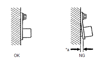
| *a | Clearance |
(a) Check the crankshaft position sensor installation condition.
OK:
Crankshaft position sensor is installed correctly.
| NG | | SECURELY REINSTALL CRANKSHAFT POSITION SENSOR |
|
| 5. | INSPECT NO. 1 CRANKSHAFT POSITION SENSOR PLATE (TEETH OF CRANKSHAFT POSITION SENSOR PLATE) |
(a) Inspect the teeth of the No. 1 crankshaft position sensor plate.
OK:
No .1 Crankshaft position sensor plate does not have any cracks or deformation.
| NG | | REPLACE NO. 1 CRANKSHAFT POSITION SENSOR PLATE |
|
| 6. | REPLACE CRANKSHAFT POSITION SENSOR |
(a) Replace the crankshaft position sensor.
Click here
|
| 7. | CHECK WHETHER DTC OUTPUT RECURS (DTC P033511, P033515, P03351F, P03352A AND/OR P033531) |
(a) Connect the Techstream to the DLC3.
(b) Turn the engine switch on (IG).
(c) Turn the Techstream on.
(d) Clear the DTCs.
Powertrain > Engine > Clear DTCs(e) Turn the engine switch off and wait for at least 30 seconds.
(f) Start the engine.
(g) Turn the Techstream on.
(h) Drive the vehicle in accordance with the driving pattern described in Confirmation Driving Pattern.
(i) Enter the following menus: Powertrain / Engine / Trouble Codes.
(j) Read the DTCs.
Powertrain > Engine > Trouble Codes| Result | Proceed to |
|---|---|
| DTCs are not output | A |
| DTC P033511, P033515, P03351F, P03352A and/or P033531 is output | B |
HINT:
If the engine does not start, replace the ECM.
| A | | END |
| B | | REPLACE ECM |
| 8. | CHECK HARNESS AND CONNECTOR (CRANKSHAFT POSITION SENSOR - ECM) |
(a) Disconnect the crankshaft position sensor connector.
(b) Disconnect the ECM connector.
(c) Measure the resistance according to the value(s) in the table below.
Standard Resistance:
| Tester Connection | Condition | Specified Condition |
|---|---|---|
| f8-3 (VC) - D2-96 (VCNE) | Always | Below 1 Ω |
| f8-3 (VC) or D2-96 (VCNE) - Body ground and other terminals | Always | 10 kΩ or higher |
| OK | | REPLACE ECM |
| NG | | REPAIR OR REPLACE HARNESS OR CONNECTOR |
 Knock Sensor 1 Bank 1 or Single Sensor Circuit Short to Battery or Open (P032515,P033015)
DESCRIPTION Refer to DTC P032511. Click here DTC No. Detection Item DTC Detection Condition Trouble Area MIL Memory Note P032515 Knock Sensor 1 Bank 1 or Single Sensor Circuit S ...
 Camshaft Position Sensor "A" Bank 1 or Single Sensor Circuit Short to Ground (P034011,P034015,P034031,P034511,P034515,P034531)
DESCRIPTION The VVT sensor (for intake camshaft) (VV1, VV2 signal) consists of a magnet and MRE (Magneto Resistance Element). The intake camshaft has a timing rotor for the VVT sensor. When the intake ...
Other materials:
Lexus RX (RX 350L, RX450h) 2016-2025 Repair Manual > Brake Master Cylinder: Inspection
INSPECTION PROCEDURE 1. INSPECT AND ADJUST BRAKE BOOSTER PUSH ROD NOTICE: Make the adjustment with no vacuum in the brake booster assembly. (Depress the brake pedal several times with the engine stopped.) HINT:
Adjustment of the brake booster push rod is required when the brake master cylinder su ...
Lexus RX (RX 350L, RX450h) 2016-2025 Repair Manual > Smart Access System With Push-button Start (for Entry Function): New Key cannot be Registered
DESCRIPTION If a new electrical key transmitter sub-assembly could not be registered, wave interference or a malfunction of the certification ECU (smart key ECU assembly), electrical key transmitter sub-assembly, ID code box (immobiliser code ECU), steering lock ECU (steering lock actuator or upper ...
Lexus RX (RX 350L, RX450h) 2016-{YEAR} Owners Manual
- For your information
- Pictorial index
- For safety and security
- Instrument cluster
- Operation of each component
- Driving
- Lexus Display Audio system
- Interior features
- Maintenance and care
- When trouble arises
- Vehicle specifications
- For owners
Lexus RX (RX 350L, RX450h) 2016-{YEAR} Repair Manual

0.0189