Lexus RX (RX 350L, RX450h) 2016-2025 Repair Manual: Knock Sensor 1 Bank 1 or Single Sensor Circuit Short to Battery or Open (P032515,P033015)
DESCRIPTION
Refer to DTC P032511.
Click here .gif)
| DTC No. | Detection Item | DTC Detection Condition | Trouble Area | MIL | Memory | Note |
|---|---|---|---|---|---|---|
| P032515 | Knock Sensor 1 Bank 1 or Single Sensor Circuit Short to Battery or Open | The knock control sensor (bank 1) output voltage is higher than 4.5 V for 1 second or more (1 trip detection logic). |
| Comes on | DTC stored | SAE Code: P0328 |
| P033015 | Knock Sensor 2 Bank 2 Circuit Short to Battery or Open | The knock control sensor (bank 2) output voltage is higher than 4.5 V for 1 second or more (1 trip detection logic). |
| Comes on | DTC stored | SAE Code: P0333 |
HINT:
When DTC P032515 or P033015 is stored, the ECM enters fail-safe mode. During fail-safe mode, the ignition timing is delayed to its maximum retardation. Fail-safe mode continues until the engine switch is turned off.
Reference: Inspection using an oscilloscope.
Click here
MONITOR DESCRIPTION
If the output voltage transmitted by the knock control sensor remains high for 1 second or more, the ECM interprets this as a malfunction in the sensor circuit, and stores this DTC.
MONITOR STRATEGY
| Related DTCs | P0328: Knock control sensor (bank 1) range check (high voltage) P0333: Knock control sensor (bank 2) range check (high voltage) |
| Required Sensors/Components (Main) | Knock control sensor |
| Required Sensors/Components (Related) | - |
| Frequency of Operation | Continuous |
| Duration | 1 second |
| MIL Operation | Immediate |
| Sequence of Operation | None |
TYPICAL ENABLING CONDITIONS
| Monitor runs whenever the following DTCs are not stored | None |
| Both of the following conditions are met | - |
| Battery voltage | 10.5 V or higher |
| Time after engine start | 5 seconds or more |
TYPICAL MALFUNCTION THRESHOLDS
| Knock control sensor voltage | Higher than 4.5 V |
CONFIRMATION DRIVING PATTERN
HINT:
-
After repair has been completed, clear the DTC and then check that the vehicle has returned to normal by performing the following All Readiness check procedure.
Click here
-
When clearing the permanent DTCs, refer to the "CLEAR PERMANENT DTC" procedure.
Click here
- Connect the Techstream to the DLC3.
- Turn the engine switch on (IG).
- Turn the Techstream on.
- Clear the DTCs (even if no DTCs are stored, perform the clear DTC procedure).
- Turn the engine switch off and wait for at least 30 seconds.
- Start the engine and wait 5 minutes [A].
- Turn the Techstream on.
- Enter the following menus: Powertrain / Engine / Trouble Codes [B].
-
Read the pending DTCs.
HINT:
- If a pending DTC is output, the system is malfunctioning.
- If a pending DTC is not output, perform the following procedure.
- Enter the following menus: Powertrain / Engine / Utility / All Readiness.
- Input the DTC: P032515 or P033015.
-
Check the DTC judgment result.
Techstream Display
Description
NORMAL
- DTC judgment completed
- System normal
ABNORMAL
- DTC judgment completed
- System abnormal
INCOMPLETE
- DTC judgment not completed
- Perform driving pattern after confirming DTC enabling conditions
HINT:
- If the judgment result is NORMAL, the system is normal.
- If the judgment result is ABNORMAL, the system is malfunctioning.
- If the judgment result is INCOMPLETE, idle the engine for 5 minutes and check the DTC judgment result again.
-
[A] to [B]: Normal judgment procedure.
The normal judgment procedure is used to complete DTC judgment and also used when clearing permanent DTCs.
- When clearing the permanent DTCs, do not disconnect the cable from the battery terminal or attempt to clear the DTCs during this procedure, as doing so will clear the universal trip and normal judgment histories.
WIRING DIAGRAM
Refer to DTC P032511.
Click here
CAUTION / NOTICE / HINT
HINT:
- DTC P032515 is for the bank 1 knock control sensor circuit.
- DTC P033015 is for the bank 2 knock control sensor circuit.
-
Bank 1 refers to the bank that includes the No. 1 cylinder*.
*: The No. 1 cylinder is the cylinder which is farthest from the transaxle.
- Bank 2 refers to the bank that does not include the No. 1 cylinder.
- Read freeze frame data using the Techstream. The ECM records vehicle and driving condition information as freeze frame data the moment a DTC is stored. When troubleshooting, freeze frame data can help determine if the vehicle was moving or stationary, if the engine was warmed up or not, if the air fuel ratio was lean or rich, and other data from the time the malfunction occurred.
PROCEDURE
| 1. | CHECK TERMINAL VOLTAGE (POWER SOURCE OF KNOCK CONTROL SENSOR) |
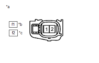
| *a | Front view of wire harness connector (to Knock Control Sensor) |
| *b | Bank 1 |
| *c | Bank 2 |
(a) Disconnect the knock control sensor connector.
(b) Turn the engine switch on (IG).
(c) Measure the voltage according to the value(s) in the table below.
Standard Voltage:
| Tester Connection | Condition | Specified Condition |
|---|---|---|
| f1-2 - f1-1 | Engine switch on (IG) | 4.5 to 5.5 V |
| f2-2 - f2-1 | Engine switch on (IG) | 4.5 to 5.5 V |
| NG | .gif) | GO TO STEP 3 |
|
.gif)
| 2. | INSPECT KNOCK CONTROL SENSOR |
(a) Inspect the knock control sensor.
Click here
HINT:
Perform "Inspection After Repair" after replacing the knock control sensor.
Click here
| OK | | GO TO STEP 4 |
| NG | | REPLACE KNOCK CONTROL SENSOR |
| 3. | CHECK HARNESS AND CONNECTOR (KNOCK CONTROL SENSOR - ECM) |
(a) Disconnect the knock control sensor connector.
(b) Disconnect the ECM connector.
(c) Measure the resistance according to the value(s) in the table below.
Standard Resistance:
| Tester Connection | Condition | Specified Condition |
|---|---|---|
| f1-2 - D2-82 (KNK1) | Always | Below 1 Ω |
| f1-1 - D2-81 (EKNK) | Always | Below 1 Ω |
| f2-2 - D2-114 (KNK2) | Always | Below 1 Ω |
| f2-1 - D2-113 (EKN2) | Always | Below 1 Ω |
| f1-2 or D2-82 (KNK1) - Other terminals | Always | 10 kΩ or higher |
| f2-2 or D2-114 (KNK2) - Other terminals | Always | 10 kΩ or higher |
| NG | | REPAIR OR REPLACE HARNESS OR CONNECTOR |
|
| 4. | CHECK WHETHER DTC OUTPUT RECURS (DTC P032515 OR P033015) |
(a) Connect the Techstream to the DLC3.
(b) Turn the engine switch on (IG).
(c) Turn the Techstream on.
(d) Clear the DTCs.
Powertrain > Engine > Clear DTCs(e) Turn the engine switch off and wait for at least 30 seconds.
(f) Turn the engine switch on (IG).
(g) Turn the Techstream on.
(h) Drive the vehicle in accordance with the driving pattern described in Confirmation Driving Pattern.
(i) Enter the following menus: Powertrain / Engine / Trouble Codes.
(j) Read the DTCs.
Powertrain > Engine > Trouble Codes| Result | Proceed to |
|---|---|
| DTCs are not output | A |
| DTC P032515 or P033015 is output | B |
| A | | CHECK FOR INTERMITTENT PROBLEMS |
| B | | REPLACE ECM |
 Knock Sensor 1 Bank 1 or Single Sensor Circuit Short to Ground (P032511,P033011)
DESCRIPTION A flat-type knock control sensor (non-resonant type) has a structure that can detect vibrations between approximately 5 kHz and 15 kHz. The knock control sensor is fitted onto the engine b ...
 Crankshaft Position Sensor "A" Circuit Short to Ground (P033511,P033515,P03351F,P03352A,P033531)
DESCRIPTION The crankshaft position sensor system consists of a crankshaft position sensor plate and Magneto Resistance Element (MRE) type sensor. The crankshaft position sensor plate has 34 teeth at ...
Other materials:
Lexus RX (RX 350L, RX450h) 2016-2025 Repair Manual > Power Seat Switch(for Rear Side): Removal
REMOVAL PROCEDURE 1. REMOVE POWER SEAT SWITCH ASSEMBLY (for 60/40 Split Seat Type RH Side) (a) Using a moulding remover A, disengage the 2 claws as shown in the illustration. Remove in this Direction (b) Disconnect the connector to remove the power seat switch assembly. 2. R ...
Lexus RX (RX 350L, RX450h) 2016-2025 Repair Manual > Air Conditioning Pressure Sensor: On-vehicle Inspection
ON-VEHICLE INSPECTION PROCEDURE 1. INSPECT AIR CONDITIONER PRESSURE SENSOR (a) Check the wire harness. (1) Disconnect the A9 air conditioner pressure sensor connector. (2) Disconnect the J42 air conditioning amplifier assembly connector. (3) Measure the resistance according to the value(s) in the ta ...
Lexus RX (RX 350L, RX450h) 2016-{YEAR} Owners Manual
- For your information
- Pictorial index
- For safety and security
- Instrument cluster
- Operation of each component
- Driving
- Lexus Display Audio system
- Interior features
- Maintenance and care
- When trouble arises
- Vehicle specifications
- For owners
Lexus RX (RX 350L, RX450h) 2016-{YEAR} Repair Manual

0.0175