Lexus RX (RX 350L, RX450h) 2016-2025 Repair Manual: Evaporative Emission System Pressure Sensor/Switch Circuit Short to Ground (P045011,P045015,P04502A,P04502F)
DTC SUMMARY
| DTC No. | Detection Item | DTC Detection Condition | Trouble Area | MIL | Memory | Note |
|---|---|---|---|---|---|---|
| P045011 | Evaporative Emission System Pressure Sensor/Switch Circuit Short to Ground | EVAP pressure less than 42.11 kPa(abs) [6.11 psi(abs)] for 0.5 seconds. |
| Comes on | DTC stored | SAE Code: P0452 |
| P045015 | Evaporative Emission System Pressure Sensor/Switch Circuit Short to Battery or Open | EVAP pressure higher than 123.761 kPa(abs) [17.95 psi(abs)] for 0.5 seconds. |
| Comes on | DTC stored | SAE Code: P0453 |
| P04502A | Evaporative Emission System Pressure Sensor/Switch Signal Stuck in Range | Canister pressure sensor output voltage does not vary in a certain time period. |
| Comes on | DTC stored | SAE Code: P0451 |
| P04502F | Evaporative Emission System Pressure Sensor/Switch Signal Erratic | Canister pressure sensor output voltage fluctuates frequently in a certain time period. |
| Comes on | DTC stored | SAE Code: P0451 |
| DTC No. | Monitoring Item | Detection Timing | Detection Logic | SAE |
|---|---|---|---|---|
| P045011 | Canister pressure sensor low input |
| 1 trip | P0452 |
| P045015 | Canister pressure sensor high input |
| 1 trip | P0453 |
| P04502A | Canister pressure sensor constant voltage |
| 2 trip | P0451 |
| P04502F | Canister pressure sensor abnormal voltage fluctuation |
| 2 trip | P0451 |
HINT:
The canister pressure sensor is built into the canister pump module.
DESCRIPTION
The description can be found in EVAP (Evaporative Emission) System.
Click here .gif)
MONITOR DESCRIPTION
-
DTC P045011: Canister pressure sensor voltage low
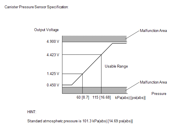
If the canister pressure sensor voltage output (pressure) is less than 0.45 V: 42.11 kPa(abs) [6.11 psi(abs)], the ECM interprets this as an open or short circuit in the canister pressure sensor or its circuit, and stops the EVAP system monitor. The ECM will illuminate the MIL and store this DTC (1 trip detection logic).
-
DTC P045015: Canister pressure sensor voltage high
If the canister pressure sensor voltage output (pressure) is higher than 4.9 V: 123.761 kPa(abs) [17.95 psi(abs)], the ECM interprets this as an open or short circuit in the canister pressure sensor or its circuit, and stops the EVAP system monitor. The ECM will illuminate the MIL and store this DTC (1 trip detection logic).
-
DTC P04502A: Canister pressure sensor abnormal voltage being constant
If the sensor voltage output does not change for 2 minutes, the ECM interprets this as the sensor being stuck, and stops the monitor. The ECM will illuminate the MIL and store this DTC (2 trip detection logic).
-
DTC P04502F: Canister pressure sensor abnormal voltage fluctuation
If the canister pressure sensor voltage output fluctuates rapidly for 10 seconds, the ECM stops the EVAP system monitor. The ECM interprets this as the canister pressure sensor voltage fluctuating, and stops the EVAP system monitor. The ECM will illuminate the MIL and store this DTC (2 trip detection logic).
MONITOR STRATEGY
| Required Sensors/Components (Main) | Canister pump module |
| Required Sensors/Components (Related) | - |
| Frequency of Operation | Continuous |
| Duration | 0.5 seconds: P0452 and P0453 Less than 2 minutes: P0451 (stuck monitoring) Less than 15 seconds: P0451 (noise monitoring) |
| MIL Operation | Immediate: P0452 and P0453 2 driving cycles: P0451 |
| Sequence of Operation | None |
TYPICAL ENABLING CONDITIONS
All| Monitor runs whenever the following DTCs are not stored | None |
| Battery voltage | 10.5 V or higher |
| Intake air temperature | 4.4°C (40°F) or higher, and less than 50°C (122°F) |
| Canister pressure sensor malfunction (P0452, P0453) | Not detected |
| Atmospheric pressure (absolute pressure) | Less than 70 kPa(abs) [10.15 psi(abs)], or 110 kPa(abs) [15.95 psi(abs)] or higher |
| Time after key-off | 5, 7 or 9.5 hours |
| All of the following conditions are met | - |
| Atmospheric pressure (absolute pressure) | 70 kPa(abs) [10.15 psi(abs)] or higher, and less than 110 kPa(abs) [15.95 psi(abs)] |
| Battery voltage | 10.5 V or higher |
| Intake air temperature | 4.4°C (40°F) or higher, and less than 50°C (122°F) |
| Canister pressure sensor malfunction (P0452, P0453) | Not detected |
| Either of the following conditions is met | A or B |
| A. Engine condition | Running |
| B. Time after key-off | 5, 7 or 9.5 hours |
| All of the following conditions are met | - |
| Either of the following conditions is met | 1 or 2 |
| 1. Engine switch | On (IG) |
| 2. Soak timer | On |
| Battery voltage | 8 V or higher |
| Starter | Off |
TYPICAL MALFUNCTION THRESHOLDS
P0451: Canister Pressure Sensor Stuck Monitoring| EVAP pressure change during reference pressure measurement | Less than 0.66 kPa(gauge) [0.096 psi(gauge)] |
| Frequency that EVAP pressure change is 0.3 kPa(gauge) [0.044 psi(gauge)] or higher | 10 times or more in 10 seconds |
| EVAP pressure sensor voltage | Less than 0.45 V (Less than 42.11 kPa(abs) [6.11 psi(abs)]) |
| EVAP pressure sensor voltage | Higher than 4.9 V (Higher than 123.761 kPa(abs) [17.95 psi(abs)]) |
CONFIRMATION DRIVING PATTERN
NOTICE:
- The Evaporative System Check (Automatic Mode) consists of 6 steps performed automatically by the Techstream. It takes a maximum of approximately 24 minutes.
- Do not perform the Evaporative System Check when the fuel tank is higher than 85% full because the cut-off valve may be closed, making the fuel tank leak check unavailable.
- Do not run the engine during this operation.
- When the temperature of the fuel is 35°C (95°F) or higher, a large amount of vapor forms and any check results become inaccurate. When performing the Evaporative System Check, keep the fuel temperature less than 35°C (95°F).
HINT:
-
After repair has been completed, clear the DTC and then check that the vehicle has returned to normal by performing the following All Readiness check procedure.
Click here
-
When clearing the permanent DTCs, refer to the "CLEAR PERMANENT DTC" procedure.
Click here
- Connect the Techstream to the DLC3.
- Turn the engine switch on (IG).
- Turn the Techstream on.
- Clear the DTCs (even if no DTCs are stored, perform the clear DTC procedure).
- Turn the engine switch off and wait for at least 30 seconds.
- Turn the engine switch on (IG) [A].
- Turn the Techstream on.
- Enter the following menus: Powertrain / Engine / Data List / Intake Air Temperature.
- Check that the intake air temperature is between 4.4 and 50°C (40 and 122°F) [B].
- Enter the following menus: Powertrain / Engine / Utility / Evaporative System Check / Automatic Mode [C].
- After the Evaporative System Check is completed, check for All Readiness by entering the following menus: Powertrain / Engine / Utility / All Readiness.
- Input the DTC: P045011, P045015, P04502A or P04502F.
-
Check the DTC judgment result.
Techstream Display
Description
NORMAL
- DTC judgment completed
- System normal
ABNORMAL
- DTC judgment completed
- System abnormal
INCOMPLETE
- DTC judgment not completed
- Perform driving pattern after confirming DTC enabling conditions
HINT:
- If the judgment result is NORMAL, the system is normal.
- If the judgment result is ABNORMAL, the system is malfunctioning.
-
[A] to [C]: Normal judgment procedure.
The normal judgment procedure is used to complete DTC judgment and also used when clearing permanent DTCs.
- When clearing the permanent DTCs, do not disconnect the cable from the battery terminal or attempt to clear the DTCs during this procedure, as doing so will clear the universal trip and normal judgment histories.
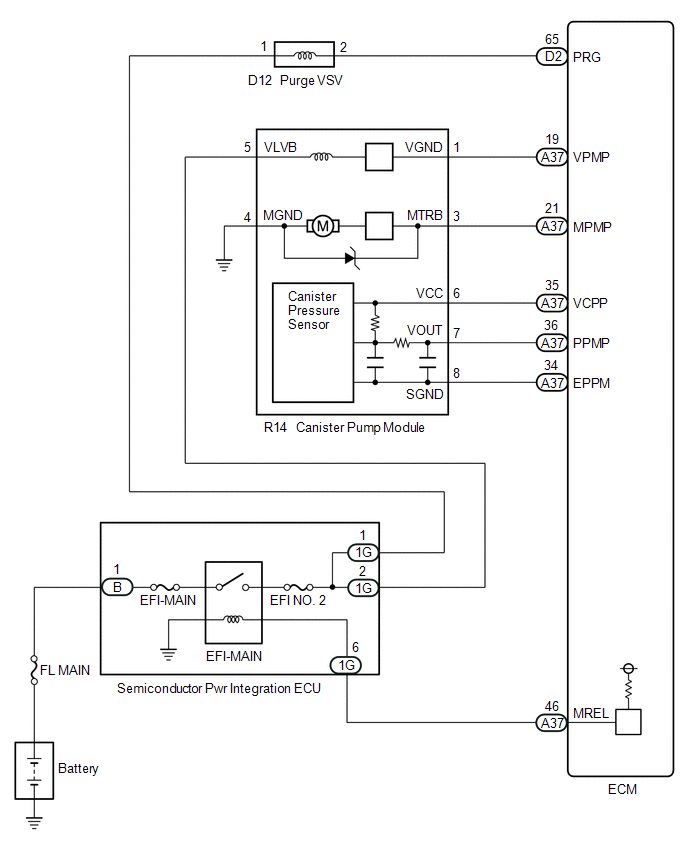
WIRING DIAGRAM
CAUTION / NOTICE / HINT
NOTICE:
- When a vehicle is brought into the workshop, leave it as it is. Do not change the vehicle condition. For example, do not tighten the fuel tank cap.
- The Techstream is required to conduct the following diagnostic troubleshooting procedure.
- Inspect the fuses for circuits related to this system before performing the following procedure.
PROCEDURE
| 1. | CONFIRM DTC AND EVAP PRESSURE |
(a) Connect the Techstream to the DLC3.
(b) Turn the engine switch on (IG) (do not start the engine).
(c) Turn the Techstream on.
(d) Enter the following menus: Powertrain / Engine / Trouble Codes.
(e) Read the DTCs.
Powertrain > Engine > Trouble Codes(f) Enter the following menus: Powertrain / Engine / Data List / Vapor Pressure Pump.
Powertrain > Engine > Data List| Tester Display |
|---|
| Vapor Pressure Pump |
(g) Read the EVAP (Evaporative Emission) pressure displayed on the Techstream.
| Display (DTC Output) | Test Result | Suspected Trouble Area | Proceed to |
|---|---|---|---|
| P045011 | Less than 42.11 kPa(abs) [6.11 psi(abs)] |
| A |
| P045015 | Higher than 123.761 kPa(abs) [17.95 psi(abs)] |
| B |
| P04502A P04502F | - | Canister pressure sensor | C |
| B | .gif) | GO TO STEP 5 |
| C | | GO TO EVAP SYSTEM |
|
.gif)
| 2. | CHECK HARNESS AND CONNECTOR (CANISTER PUMP MODULE - ECM) |
(a) Disconnect the ECM connector.
(b) Measure the resistance according to the value(s) in the table below.
| Tester Connection | Condition | Specified Condition | Suspected Trouble Area | Proceed to |
|---|---|---|---|---|
| A37-36 (PPMP) - Body ground | Always | Below 10 Ω |
| A |
| 10 kΩ or higher |
| B |
| B | | GO TO STEP 4 |
|
| 3. | CHECK HARNESS AND CONNECTOR (CANISTER PUMP MODULE - ECM) |
(a) Disconnect the canister pump module connector.
(b) Disconnect the ECM connector.
(c) Measure the resistance according to the value(s) in the table below.
| Tester Connection | Condition | Specified Condition | Suspected Trouble Area | Proceed to |
|---|---|---|---|---|
| A37-36 (PPMP) - Body ground | Always | 10 kΩ or higher | Short in canister pressure sensor circuit | A |
| Below 10 Ω | Short in wire harness or connector (canister pressure sensor - ECM) | B |
| A | | GO TO STEP 6 |
| B | | GO TO STEP 7 |
| 4. | REPLACE ECM |
(a) Replace the ECM.
Click here
| NEXT | | GO TO STEP 8 |
| 5. | CHECK HARNESS AND CONNECTOR (CANISTER PUMP MODULE - ECM) |
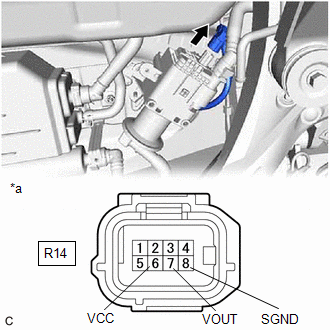
| *a | Front view of wire harness connector (to Canister Pump Module) |
(a) Disconnect the canister pump module connector.
(b) Measure the resistance according to the value(s) in the table below.
Standard Resistance:
| Tester Connection | Condition | Specified Condition |
|---|---|---|
| R14-8 (SGND) - Body ground | Always | 100 Ω or less |
(c) Turn the engine switch on (IG).
(d) Measure the voltage according to the value(s) in the table below.
Standard Voltage:
| Tester Connection | Condition | Specified Condition |
|---|---|---|
| R14-6 (VCC) - Body ground | Engine switch on (IG) | 4.5 to 5.5 V |
| R14-7 (VOUT) - Body ground | Engine switch on (IG) | 4.5 to 5.5 V |
| Test Result | Suspected Trouble Area | Proceed to |
|---|---|---|
| Voltage and resistance within standard ranges | Open in canister pressure sensor circuit | A |
| Voltage and/or resistance outside standard ranges | Open in wire harness or connector (canister pressure sensor - ECM) | B |
| B | | GO TO STEP 7 |
|
| 6. | REPLACE CANISTER PUMP MODULE |
(a) Replace the canister pump module.
Click here
NOTICE:
- When replacing the canister pump module, check the canister pump module interior, canister interior and related pipes for water, fuel and other liquids. If liquids are present, check for disconnections and/or cracks in the following: 1) the pipe from the air inlet port to the canister pump module; 2) the canister filter; and 3) the fuel tank vent hose. If liquids are present in the canister interior, replace the canister and canister pump module together.
- Check for filter blockage in the canister. If the charcoal filter inside the canister is clogged, replace the canister and canister pump module together.
- Check for filter blockage in the canister filter. If the canister filter has blockages, replace the canister filter.
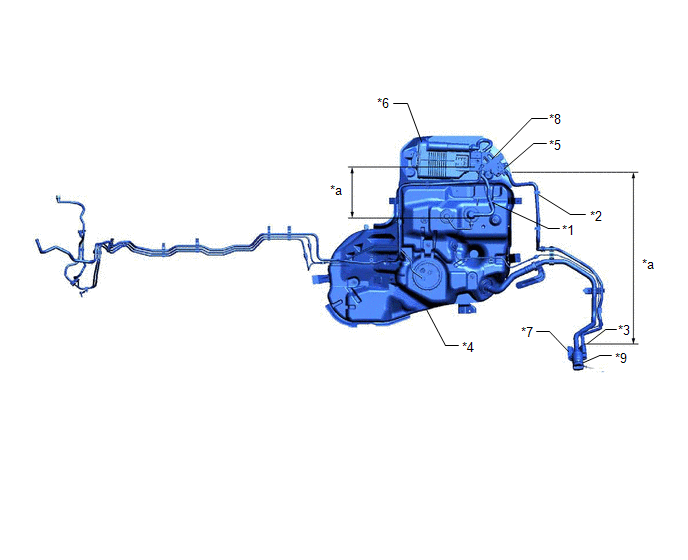
| *1 | Fuel Tank Vent Hose | *2 | Vent Hose |
| *3 | Air Inlet Port | *4 | Fuel Tank |
| *5 | Canister Pump Module | *6 | Canister |
| *7 | Canister Filter | *8 | No. 1 Charcoal Canister Filter |
| *9 | Fuel Tank Cap | - | - |
| *a | Inspection Area (check for disconnection and/or cracks) | - | - |
| NEXT | | GO TO STEP 8 |
| 7. | REPAIR OR REPLACE HARNESS OR CONNECTOR (CANISTER PUMP MODULE - ECM) |
(a) Repair or replace the harness or connector (canister pump module - ECM).
|
| 8. | CHECK WHETHER DTC OUTPUT RECURS (DTC P045011 OR P045015) |
(a) Connect the Techstream to the DLC3.
(b) Turn the engine switch on (IG).
(c) Turn the Techstream on.
(d) Clear the DTCs.
Powertrain > Engine > Clear DTCs(e) Turn the engine switch off and wait for at least 30 seconds.
(f) Turn the engine switch on (IG).
(g) Turn the Techstream on.
(h) Perform the Evaporative System Check using the Techstream, referring to Confirmation Driving Pattern.
(i) Enter the following menus: Powertrain / Engine / Utility / All Readiness.
Powertrain > Engine > Utility| Tester Display |
|---|
| All Readiness |
(j) Input the DTC: P045011 or P045015.
(k) Check the DTC judgment result.
| Techstream Display | Description |
|---|---|
| NORMAL |
|
| ABNORMAL |
|
| INCOMPLETE |
|
| N/A |
|
| NEXT | | END |
 Evaporative Emission System Incorrect Purge Flow Actuator Stuck On (P04417E,P04417F,P04419C)
DTC SUMMARY DTC No. Detection Item DTC Detection Condition Trouble Area MIL Memory Note P04417E Evaporative Emission System Incorrect Purge Flow Actuator Stuck On Leak detection ...
 Evaporative Emission System Leak Detected (Large Leak) (P045500,P045600)
DTC SUMMARY DTC No. Detection Item DTC Detection Condition Trouble Area MIL Memory Note P045500 Evaporative Emission System Leak Detected (Large Leak) Leak detection pump create ...
Other materials:
Lexus RX (RX 350L, RX450h) 2016-2025 Repair Manual > Electrical Key Oscillator (for Outside Luggage Compartment): Removal
REMOVAL CAUTION / NOTICE / HINT The necessary procedures (adjustment, calibration, initialization, or registration) that must be performed after parts are removed and installed, or replaced during electrical key removal/installation are shown below. Necessary Procedures After Parts Removed/Installed ...
Lexus RX (RX 350L, RX450h) 2016-2025 Repair Manual > Window Defogger System: Precaution
PRECAUTION PRECAUTION FOR DISCONNECTING CABLE FROM NEGATIVE BATTERY TERMINAL NOTICE: When disconnecting the cable from the negative (-) battery terminal, initialize the following systems after the cable is reconnected. System Name See Procedure Lane Control System Intelligent Clear ...
Lexus RX (RX 350L, RX450h) 2016-{YEAR} Owners Manual
- For your information
- Pictorial index
- For safety and security
- Instrument cluster
- Operation of each component
- Driving
- Lexus Display Audio system
- Interior features
- Maintenance and care
- When trouble arises
- Vehicle specifications
- For owners
Lexus RX (RX 350L, RX450h) 2016-{YEAR} Repair Manual

0.0157