Lexus RX (RX 350L, RX450h) 2016-2026 Repair Manual: Fuel Level Sensor "A" Signal Stuck In Range (P04602A)
DESCRIPTION
Refer to DTC P046012.
Click here .gif)
| DTC No. | Detection Item | DTC Detection Condition | Trouble Area | MIL | Memory | Note |
|---|---|---|---|---|---|---|
| P04602A | Fuel Level Sensor "A" Signal Stuck In Range | The change in the fuel sender gauge value is below the threshold when a certain amount of fuel is calculated to have been consumed. (1 trip detection logic). |
| Comes on | DTC stored | SAE Code: P0461 |
MONITOR DESCRIPTION
When the fuel sender gauge assembly output value changes less than a specified amount, when compared to the fuel consumption calculated from the fuel injection volume, the ECM will detect a malfunction, illuminate the MIL and store a DTC.
MONITOR STRATEGY
| Related DTCs | P0461: Fuel level sensor stuck |
| Required Sensors/Components (Main) | Fuel level sensor |
| Required Sensors/Components (Related) | - |
| Frequency of Operation | Continuous |
| Duration | Less than 10 seconds |
| MIL Operation | 1 driving cycles |
| Sequence of Operation | None |
TYPICAL ENABLING CONDITIONS
| Lost communication with instrument panel cluster control module (U0155) | Not detected |
| Fuel level sensor circuit malfunction (P0462, P0463) | Not detected |
| Either of the following conditions is met | Condition A or B |
| A. Battery voltage | 8 V or higher |
| B. Check mode | On |
| Fuel level sensor output via CAN | Received |
| Engine switch | On (IG) |
TYPICAL MALFUNCTION THRESHOLDS
| One of the following conditions is met | A, B or C |
| A. Accumulated volume of injected fuel during (a) is met at high fuel level | 31.5 L or more |
| B. Accumulated volume of injected fuel during (a) is met at middle fuel level | 9.6 L or more |
| C. Accumulated volume of injected fuel during (a) is met at low fuel level | 25.6 L or more |
| (a) Smoothed fuel level sensor output (Maximum - Minimum) | Less than 3.6 L |
CONFIRMATION DRIVING PATTERN
HINT:
-
After repair has been completed, clear the DTC and then check that the vehicle has returned to normal by performing the following All Readiness check procedure.
Click here
-
When clearing the permanent DTCs, refer to the "CLEAR PERMANENT DTC" procedure.
Click here
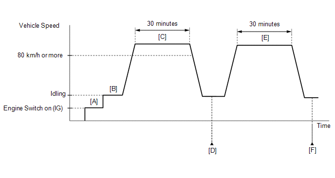
- Connect the Techstream to the DLC3.
- Turn the engine switch on (IG).
- Turn the Techstream on.
- Clear the DTCs (even if no DTCs are stored, perform the clear DTC procedure).
- Turn the engine switch off and wait for at least 30 seconds.
- Turn the engine switch on (IG) [A].
- Turn the Techstream on.
- Start the engine [B].
- Drive the vehicle at 80 km/h (50 mph) or more for 30 minutes [C].
- Enter the following menus: Powertrain / Engine / Trouble Codes [D].
-
Read the pending DTCs.
HINT:
- If a pending DTC is output, the system is malfunctioning.
- If a pending DTC is not output, perform the following procedure.
- Enter the following menus: Powertrain / Engine / Utility / All Readiness.
- Input the DTC: P04602A.
-
Check the DTC judgment result.
Techstream Display
Description
NORMAL
- DTC judgment completed
- System normal
ABNORMAL
- DTC judgment completed
- System abnormal
INCOMPLETE
- DTC judgment not completed
- Perform driving pattern after confirming DTC enabling conditions
HINT:
- If the judgment result shows NORMAL, the system is normal.
- If the judgment result shows ABNORMAL, the system has a malfunction.
- If the judgment result is INCOMPLETE, perform steps [E] through [F] again.
-
[A] to [D]: Normal judgment procedure.
The normal judgment procedure is used to complete DTC judgment and also used when clearing permanent DTCs.
- When clearing the permanent DTCs, do not disconnect the cable from the battery terminal or attempt to clear the DTCs during this procedure, as doing so will clear the universal trip and normal judgment histories.
- Drive the vehicle at 80 km/h (50 mph) or more for 30 minutes [E].
- Enter the following menus: Powertrain / Engine / Trouble Codes [F].
-
Read the pending DTCs.
HINT:
- If a pending DTC is output, the system is malfunctioning.
- If a pending DTC is not output, perform the following procedure.
- Enter the following menus: Powertrain / Engine / Utility / All Readiness.
- Input the DTC: P04602A.
-
Check the DTC judgment result.
Techstream Display
Description
NORMAL
- DTC judgment completed
- System normal
ABNORMAL
- DTC judgment completed
- System abnormal
INCOMPLETE
- DTC judgment not completed
- Perform driving pattern after confirming DTC enabling conditions
HINT:
- If the judgment result shows NORMAL, the system is normal.
- If the judgment result shows ABNORMAL, the system has a malfunction.
-
[A] to [F]: Normal judgment procedure.
The normal judgment procedure is used to complete DTC judgment and also used when clearing permanent DTCs.
- When clearing the permanent DTCs, do not disconnect the cable from the battery terminal or attempt to clear the DTCs during this procedure, as doing so will clear the universal trip and normal judgment histories.
CAUTION / NOTICE / HINT
HINT:
Read freeze frame data using the Techstream. The ECM records vehicle and driving condition information as freeze frame data the moment a DTC is stored. When troubleshooting, freeze frame data can help determine if the vehicle was moving or stationary, if the engine was warmed up or not, if the air fuel ratio was lean or rich, and other data from the time the malfunction occurred.
PROCEDURE
| 1. | INTERVIEW THE CUSTOMER |
(a) Interview the customer for details about when the they refuel the vehicle.
HINT:
When the fuel tank is full, if the vehicle is repeatedly driven a short distance and then refueled, the fuel sender gauge output value will not change. In this case, the ECM may judge that the fuel sender gauge is stuck and store DTC P04602A. If the vehicle was driven in this manner, as the DTC was stored due to a user action, clear the DTCs without performing troubleshooting and return the vehicle to the customer.
|
.gif)
| 2. | INSPECT FUEL SENDER GAUGE ASSEMBLY |
(a) Remove the fuel sender gauge assembly.
Click here
(b) Inspect the fuel sender gauge assembly.
Click here
| OK | .gif) | CHECK FOR INTERMITTENT PROBLEMS |
| NG | | REPLACE FUEL SENDER GAUGE ASSEMBLY |
 Fuel Level Sensor "A" Circuit Short to Battery (P046012,P046014)
DESCRIPTION The fuel sender gauge is located inside the fuel tank and measures the amount of fuel. The fuel sender gauge converts the fuel level in the fuel tank into a voltage value and outputs it to ...
 Vehicle Speed Sensor "A" No Signal (P050031)
DESCRIPTION Vehicles, which are equipped with ABS (Anti-lock Brake System), detect the vehicle speed using the skid control ECU (brake actuator assembly) and speed sensor. The speed sensor monitors th ...
Other materials:
Lexus RX (RX 350L, RX450h) 2016-2026 Repair Manual > Navigation System: Cursor or Map Rotates when Vehicle Stopped
PROCEDURE 1. CHECK CONDITION (a) Check with the customer if the vehicle has been turned by a turntable. OK: Vehicle has not been turned by a turntable. HINT: If the vehicle is turned on a turntable with the engine switch on (IG), the system may store the angular velocity. As a result, t ...
Lexus RX (RX 350L, RX450h) 2016-2026 Repair Manual > Power Seat Switch(for Rear Side): Components
COMPONENTS ILLUSTRATION *A for 60/40 Split Seat Type RH Side - - *1 POWER SEAT SWITCH ASSEMBLY *2 REAR POWER SEAT SWITCH RH *3 RECLINING REMOTE CONTROL BEZEL RH - - ILLUSTRATION *A for 60/40 Split Seat Type LH Side - - *1 POWER SEAT SWITCH ASSEMBLY ...
Lexus RX (RX 350L, RX450h) 2016-{YEAR} Owners Manual
- For your information
- Pictorial index
- For safety and security
- Instrument cluster
- Operation of each component
- Driving
- Lexus Display Audio system
- Interior features
- Maintenance and care
- When trouble arises
- Vehicle specifications
- For owners
Lexus RX (RX 350L, RX450h) 2016-{YEAR} Repair Manual

0.0124