Lexus RX (RX 350L, RX450h) 2016-2026 Repair Manual: Brake Switch "A"/"B" Signal Cross Coupled (P05042B)
DESCRIPTION
The stop light switch assembly is a duplex system that transmits two signals: STP and ST1-. These two signals are used by the ECM to monitor whether or not the brake system is working properly. If the signals, which indicate the brake pedal is being depressed and released, are detected simultaneously, the ECM interprets this as a malfunction in the stop light switch assembly and stores this DTC.
HINT:
The normal signal conditions are as shown in the table below.
| Signal (ECM Terminal) | Brake Pedal Released | In Transition | Brake Pedal Depressed |
|---|---|---|---|
| STP | OFF | ON | ON |
| ST1- | ON | ON | OFF |
- [OFF] denotes ground potential.
- [ON] denotes battery potential (+B).
On the Techstream, Data List item Stop Light SW is ON when the brake pedal is depressed.
| DTC No. | Detection Item | DTC Detection Condition | Trouble Area | MIL | Memory | Note |
|---|---|---|---|---|---|---|
| P05042B | Brake Switch "A"/"B" Signal Cross Coupled | Conditions (a) and (b) are met for 0.5 seconds or more (1 trip detection logic): (a) Engine switch on (IG) (b) STP signal OFF when ST1- signal OFF |
| Does not come on | DTC stored | SAE Code: P0504 |
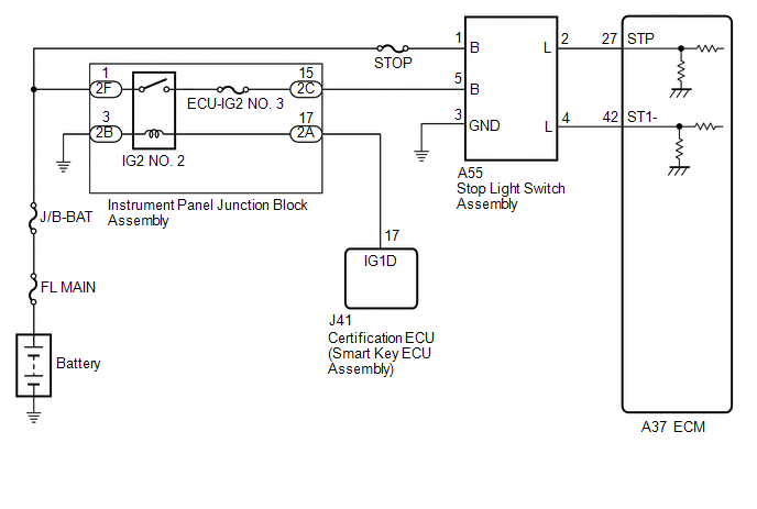
WIRING DIAGRAM
CAUTION / NOTICE / HINT
NOTICE:
Inspect the fuses for circuits related to this system before performing the following procedure.
HINT:
-
Stop light switch assembly conditions can be checked using the Techstream.
- Connect the Techstream to the DLC3.
- Turn the engine switch on (IG).
- Turn the Techstream on.
- Enter the following menus: Powertrain / Engine / Data List / Stop Light SW.
-
Check the Data List indication when the brake pedal is depressed and released.
Brake Pedal Operation
Stop Light SW
Depressed
ON
Released
OFF
- Read freeze frame data using the Techstream. The ECM records vehicle and driving condition information as freeze frame data the moment a DTC is stored. When troubleshooting, freeze frame data can help determine if the vehicle was moving or stationary, if the engine was warmed up or not, if the air fuel ratio was lean or rich, and other data from the time the malfunction occurred.
PROCEDURE
| 1. | CHECK TERMINAL VOLTAGE (POWER SOURCE OF STOP LIGHT SWITCH ASSEMBLY) |
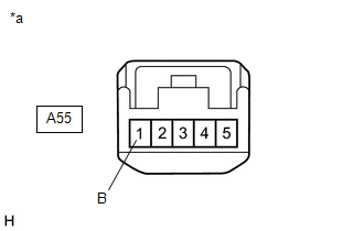
| *a | Front view of wire harness connector (to Stop Light Switch Assembly) |
(a) Disconnect the stop light switch assembly connector.
(b) Measure the voltage according to the value(s) in the table below.
Standard Voltage:
| Tester Connection | Condition | Specified Condition |
|---|---|---|
| A55-1 (B) - Body ground | Always | 11 to 14 V |
| NG | .gif) | REPAIR OR REPLACE HARNESS OR CONNECTOR (BATTERY - STOP LIGHT SWITCH ASSEMBLY) |
|
.gif)
| 2. | CHECK TERMINAL VOLTAGE (POWER SOURCE OF STOP LIGHT SWITCH ASSEMBLY) |
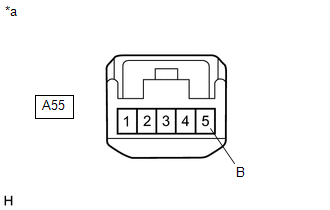
| *a | Front view of wire harness connector (to Stop Light Switch Assembly) |
(a) Disconnect the stop light switch assembly connector.
(b) Turn the engine switch on (IG).
(c) Measure the voltage according to the value(s) in the table below.
Standard Voltage:
| Tester Connection | Condition | Specified Condition |
|---|---|---|
| A55-5 (B) - Body ground | Engine switch on (IG) | 11 to 14 V |
| NG | | GO TO STEP 6 |
|
| 3. | CHECK HARNESS AND CONNECTOR (STOP LIGHT SWITCH ASSEMBLY - BODY GROUND) |
(a) Disconnect the stop light switch assembly connector.
(b) Measure the resistance according to the value(s) in the table below.
Standard Resistance:
| Tester Connection | Condition | Specified Condition |
|---|---|---|
| A55-3 (GND) - Body ground | Always | Below 1 Ω |
| NG | | REPAIR OR REPLACE HARNESS OR CONNECTOR |
|
| 4. | CHECK TERMINAL VOLTAGE (STP AND ST1- VOLTAGE) |
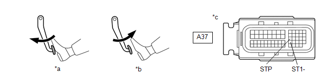
| *a | Brake Pedal Depressed | *b | Brake Pedal Released |
| *c | Front view of wire harness connector (to ECM) | - | - |
(a) Disconnect the ECM connector.
(b) Turn the engine switch on (IG).
(c) Measure the voltage according to the value(s) in the table below.
Standard Voltage:
| Tester Connection | Brake Pedal Operation | Specified Condition |
|---|---|---|
| A37-42 (ST1-) - Body ground | Released | 7.5 to 14 V |
| Depressed | Below 1.5 V | |
| A37-27 (STP) - Body ground | Released | Below 1.5 V |
| Depressed | 7.5 to 14 V |
| OK | | REPLACE ECM |
.gif)
|
| 5. | CHECK HARNESS AND CONNECTOR (STOP LIGHT SWITCH ASSEMBLY - ECM) |
(a) Disconnect the stop light switch assembly connector.
(b) Disconnect the ECM connector.
(c) Measure the resistance according to the value(s) in the table below.
Standard Resistance:
| Tester Connection | Condition | Specified Condition |
|---|---|---|
| A55-4 (L) - A37-42 (ST1-) | Always | Below 1 Ω |
| A55-2 (L) - A37-27 (STP) | Always | Below 1 Ω |
| A55-4 (L) or A37-42 (ST1-) - Body ground and other terminals | Always | 10 kΩ or higher |
| A55-2 (L) or A37-27 (STP) - Body ground and other terminals | Always | 10 kΩ or higher |
| OK | | REPLACE STOP LIGHT SWITCH ASSEMBLY |
| NG | | REPAIR OR REPLACE HARNESS OR CONNECTOR |
| 6. | CHECK HARNESS AND CONNECTOR (INSTRUMENT PANEL JUNCTION BLOCK ASSEMBLY - STOP LIGHT SWITCH ASSEMBLY) |
(a) Disconnect the instrument panel junction block assembly connector.
(b) Disconnect the stop light switch assembly connector.
(c) Measure the resistance according to the value(s) in the table below.
Standard Resistance:
| Tester Connection | Condition | Specified Condition |
|---|---|---|
| 2C-15 - A55-5 (B) | Always | Below 1 Ω |
| 2C-15 or A55-5 (B) - Body ground and other terminals | Always | 10 kΩ or higher |
| NG | | REPAIR OR REPLACE HARNESS OR CONNECTOR |
|
| 7. | CHECK HARNESS AND CONNECTOR (INSTRUMENT PANEL JUNCTION BLOCK ASSEMBLY - BODY GROUND) |
(a) Disconnect the instrument panel junction block assembly connector.
(b) Measure the resistance according to the value(s) in the table below.
Standard Resistance:
| Tester Connection | Condition | Specified Condition |
|---|---|---|
| 2B-3 - Body ground | Always | Below 1 Ω |
| NG | | REPAIR OR REPLACE HARNESS OR CONNECTOR |
|
| 8. | CHECK TERMINAL VOLTAGE (POWER SOURCE OF INSTRUMENT PANEL JUNCTION BLOCK ASSEMBLY) |
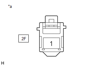
| *a | Front view of wire harness connector (to Instrument Panel Junction Block Assembly) |
(a) Disconnect the instrument panel junction block assembly connector.
(b) Measure the voltage according to the value(s) in the table below.
Standard Voltage:
| Tester Connection | Condition | Specified Condition |
|---|---|---|
| 2F-1 - Body ground | Always | 11 to 14 V |
| NG | | REPAIR OR REPLACE HARNESS OR CONNECTOR |
|
| 9. | CHECK TERMINAL VOLTAGE (POWER SOURCE OF INSTRUMENT PANEL JUNCTION BLOCK ASSEMBLY) |
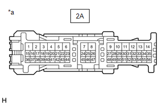
| *a | Front view of wire harness connector (to Instrument Panel Junction Block Assembly) |
(a) Disconnect the instrument panel junction block assembly connector.
(b) Turn the engine switch on (IG).
(c) Measure the voltage according to the value(s) in the table below.
Standard Voltage:
| Tester Connection | Condition | Specified Condition |
|---|---|---|
| 2A-17 - Body ground | Engine switch on (IG) | 11 to 14 V |
| OK | | REPLACE INSTRUMENT PANEL JUNCTION BLOCK ASSEMBLY |
|
| 10. | CHECK HARNESS AND CONNECTOR (CERTIFICATION ECU (SMART KEY ECU ASSEMBLY) - INSTRUMENT PANEL JUNCTION BLOCK ASSEMBLY) |
(a) Disconnect the certification ECU (smart key ECU assembly) connector.
(b) Disconnect the instrument panel junction block assembly connector.
(c) Measure the resistance according to the value(s) in the table below.
Standard Resistance:
| Tester Connection | Condition | Specified Condition |
|---|---|---|
| J41-17 (IG1D) - 2A-17 | Always | Below 1 Ω |
| J41-17 (IG1D) or 2A-17 - Body ground and other terminals | Always | 10 kΩ or higher |
| OK | | CHECK SMART ACCESS SYSTEM WITH PUSH-BUTTON START (for Start Function) |
| NG | | REPAIR OR REPLACE HARNESS OR CONNECTOR |
 Cold Start Idle Control System Performance (P050A00)
MONITOR DESCRIPTION This monitor will run when the engine is started at an engine coolant temperature of -10 to 50°C (14 to 122°F). The DTC will be stored after the engine idles for 13 seconds (2 tr ...
 Cold Start Ignition Timing Performance (P050B00)
MONITOR DESCRIPTION This monitor will run when the engine is started at an engine coolant temperature of -10 to 50°C (14 to 122°F). The DTC is stored after the engine idles for 13 seconds (2 trip de ...
Other materials:
Lexus RX (RX 350L, RX450h) 2016-2026 Repair Manual > Differential Oil Seal: Components
COMPONENTS ILLUSTRATION *1 FRONT WHEEL OPENING EXTENSION PAD LH *2 NO. 3 ENGINE UNDER COVER *3 FRONT FENDER APRON SEAL LH - - ILLUSTRATION *1 DRIVE SHAFT BEARING BRACKET *2 FRONT DRIVE SHAFT OIL SEAL LH *3 FRONT DRIVE SHAFT OIL SEAL RH *4 O-RING *5 RE ...
Lexus RX (RX 350L, RX450h) 2016-2026 Repair Manual > Seat: Seat Heater Control(for Front Side)
ComponentsCOMPONENTS ILLUSTRATION *1 SEAT HEATER CONTROL SUB-ASSEMBLY - - RemovalREMOVAL CAUTION / NOTICE / HINT The necessary procedures (adjustment, calibration, initialization or registration) that must be performed after parts are removed and installed, or replaced during seat heate ...
Lexus RX (RX 350L, RX450h) 2016-{YEAR} Owners Manual
- For your information
- Pictorial index
- For safety and security
- Instrument cluster
- Operation of each component
- Driving
- Lexus Display Audio system
- Interior features
- Maintenance and care
- When trouble arises
- Vehicle specifications
- For owners
Lexus RX (RX 350L, RX450h) 2016-{YEAR} Repair Manual

0.0156