Lexus RX (RX 350L, RX450h) 2016-2025 Repair Manual: System Voltage Circuit Short to Ground or Open (P056014)
MONITOR DESCRIPTION
The battery supplies electricity to the ECM even when the engine switch is off. This power allows the ECM to store data such as DTC history, freeze frame data and fuel trim values. If the battery voltage falls below a minimum level, the memory is cleared and the ECM determines that there is a malfunction in the power supply circuit. The next time the engine is started, the ECM will illuminate the MIL and store this DTC.
| DTC No. | Detection Item | DTC Detection Condition | Trouble Area | MIL | Memory | Note |
|---|---|---|---|---|---|---|
| P056014 | System Voltage Circuit Short to Ground or Open | An open or short in the ECM backup power source circuit (1 trip detection logic). |
| Comes on | DTC stored | SAE Code: P0562 |
MONITOR STRATEGY
| Related DTCs | P0562: ECM system voltage range check (low voltage) |
| Required Sensors/Components (Main) | ECM |
| Required Sensors/Components (Related) | - |
| Frequency of Operation | Continuous |
| Duration | 3 seconds |
| MIL Operation | Immediate |
| Sequence of Operation | None |
TYPICAL ENABLING CONDITIONS
| Monitor runs whenever the following DTCs are not stored | None |
| All of the following conditions are met | - |
| Battery voltage | 8 V or higher |
| Engine switch | On (IG) |
| Starter | Off |
TYPICAL MALFUNCTION THRESHOLDS
| Both of the following conditions are met | - |
| Battery voltage (BATT) | Less than 3.5 V |
| Electronic throttle actuator power supply voltage (+BM) | Less than 3.5 V |
CONFIRMATION DRIVING PATTERN
HINT:
-
After repair has been completed, clear the DTC and then check that the vehicle has returned to normal by performing the following All Readiness check procedure.
Click here
.gif)
-
When clearing the permanent DTCs, refer to the "CLEAR PERMANENT DTC" procedure.
Click here
- Connect the Techstream to the DLC3.
- Turn the engine switch on (IG).
- Turn the Techstream on.
- Clear the DTCs (even if no DTCs are stored, perform the clear DTC procedure).
- Turn the engine switch off and wait for at least 30 seconds.
- Turn the engine switch on (IG).
- Turn the Techstream on.
- Wait 5 seconds or more [A].
- Enter the following menus: Powertrain / Engine / Trouble Codes [B].
-
Read the pending DTCs.
HINT:
- If a pending DTC is output, the system is malfunctioning.
- If a pending DTC is not output, perform the following procedure.
- Enter the following menus: Powertrain / Engine / Utility / All Readiness.
- Input the DTC: P056014.
-
Check the DTC judgment result.
Techstream Display
Description
NORMAL
- DTC judgment completed
- System normal
ABNORMAL
- DTC judgment completed
- System abnormal
INCOMPLETE
- DTC judgment not completed
- Perform driving pattern after confirming DTC enabling conditions
HINT:
- If the judgment result is NORMAL, the system is normal.
- If the judgment result is ABNORMAL, the system is malfunctioning.
-
[A] to [B]: Normal judgment procedure.
The normal judgment procedure is used to complete DTC judgment and also used when clearing permanent DTCs.
- When clearing the permanent DTCs, do not disconnect the cable from the battery terminal or attempt to clear the DTCs during this procedure, as doing so will clear the universal trip and normal judgment histories.
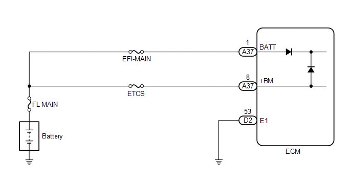
WIRING DIAGRAM
CAUTION / NOTICE / HINT
NOTICE:
- Inspect the fuses for circuits related to this system before performing the following procedure.
-
After turning engine switch off, waiting time may be required before disconnecting the cable from the negative (-) battery terminal. Therefore, make sure to read the disconnecting the cable from the negative (-) battery terminal notices before proceeding with work.
Click here
HINT:
Read freeze frame data using the Techstream. The ECM records vehicle and driving condition information as freeze frame data the moment a DTC is stored. When troubleshooting, freeze frame data can help determine if the vehicle was moving or stationary, if the engine was warmed up or not, if the air fuel ratio was lean or rich, and other data from the time the malfunction occurred.
PROCEDURE
| 1. | INSPECT BATTERY |
(a) Inspect the battery.
Click here
OK:
Battery voltage is between 11 to 14 V.
| NG | .gif) | CHARGE OR REPLACE BATTERY |
|
.gif)
| 2. | CHECK BATTERY TERMINAL |
(a) Check that the battery terminals are not loose or corroded.
OK:
Battery terminals are not loose or corroded
| NG | | REPAIR OR REPLACE BATTERY TERMINAL |
|
| 3. | CHECK HARNESS AND CONNECTOR (POWER SOURCE OF ECM) |
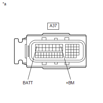
| *a | Front view of wire harness connector (to ECM) |
(a) Disconnect the ECM connector.
(b) Measure the voltage according to the value(s) in the table below.
Standard Voltage:
| Tester Connection | Condition | Specified Condition |
|---|---|---|
| A37-1 (BATT) - Body ground | Always | 11 to 14 V |
| A37-8 (+BM) - Body ground | Always | 11 to 14 V |
| NG | | REPAIR OR REPLACE HARNESS OR CONNECTOR (BATTERY - ECM) |
|
| 4. | CHECK WHETHER DTC OUTPUT RECURS (DTC P056014) |
(a) Connect the Techstream to the DLC3.
(b) Turn the engine switch on (IG).
(c) Turn the Techstream on.
(d) Clear the DTCs.
Powertrain > Engine > Clear DTCs(e) Turn the engine switch off and wait for at least 30 seconds.
(f) Turn the engine switch on (IG).
(g) Turn the Techstream on.
(h) Wait 5 seconds or more.
(i) Enter the following menus: Powertrain / Engine / Trouble Codes.
(j) Read the DTCs.
Powertrain > Engine > Trouble Codes| Result | Proceed to |
|---|---|
| DTCs are not output | A |
| DTC P056014 is output | B |
| A | | CHECK FOR INTERMITTENT PROBLEMS |
| B | | REPLACE ECM |
 Cold Start Ignition Timing Performance (P050B00)
MONITOR DESCRIPTION This monitor will run when the engine is started at an engine coolant temperature of -10 to 50°C (14 to 122°F). The DTC is stored after the engine idles for 13 seconds (2 trip de ...
 Thermostat Heater Control Circuit Short to Battery (P059712)
DESCRIPTION An electric heater is equipped to the temperature sensing portion of the thermostat. During normal driving, current does not flow to the heater and the thermostat functions as an ordinary ...
Other materials:
Lexus RX (RX 350L, RX450h) 2016-2025 Owners Manual > Do-it-yourself
maintenance: Tire inflation pressure
Tire inflation pressure
The recommended cold tire inflation
pressure and tire size are displayed on
the tire and loading information label.
Inspection and adjustment procedure
Tire valve
Tire pressure gauge
1. Remove the tire valve cap.
2. Press the tip of the tire pressure gauge o ...
Lexus RX (RX 350L, RX450h) 2016-2025 Owners Manual > Do-it-yourself
maintenance: Tires
Replace or rotate tires in accordance with maintenance schedules and
treadwear.
Checking tires
Check if the treadwear indicators are showing on the tires. Also check the
tires
for uneven wear, such as excessive wear on one side of the tread.
Check the spare tire condition and pressure if n ...
Lexus RX (RX 350L, RX450h) 2016-{YEAR} Owners Manual
- For your information
- Pictorial index
- For safety and security
- Instrument cluster
- Operation of each component
- Driving
- Lexus Display Audio system
- Interior features
- Maintenance and care
- When trouble arises
- Vehicle specifications
- For owners
Lexus RX (RX 350L, RX450h) 2016-{YEAR} Repair Manual

0.0195