Lexus RX (RX 350L, RX450h) 2016-2025 Repair Manual: Throttle/Pedal Position Sensor/Switch "D" Circuit Short to Battery (P212012,P212014,P21201F,P212512,P212514,P21251F,P21382B)
DESCRIPTION
HINT:
- This Electronic Throttle Control System (ETCS) does not use a throttle cable.
- These DTCs relate to the accelerator pedal position sensor.
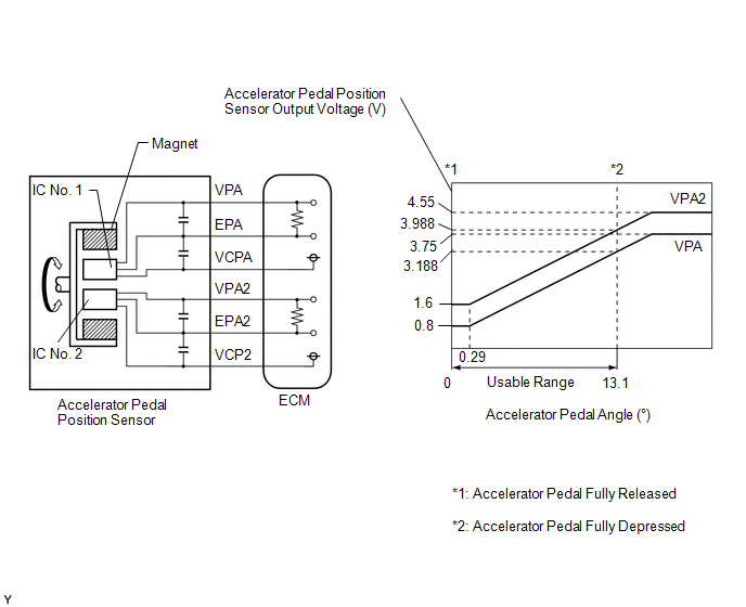
The accelerator pedal position sensor is built into the accelerator pedal sensor assembly and has 2 sensor circuits: VPA (main) and VPA2 (sub). This sensor is a non-contact type sensor and uses Hall-effect elements in order to yield accurate signals even in extreme driving conditions, such as at high speeds as well as very low speeds. The voltage, which is applied to terminals VPA and VPA2 of the ECM, varies between 0.5 V and 4.75 V in proportion to the operating angle of the accelerator pedal (throttle valve). A signal from VPA indicates the actual accelerator pedal opening angle (throttle valve opening angle) and is used for engine control. A signal from VPA2 conveys the status of the VPA circuit and is used to check the accelerator pedal position sensor itself.
The ECM monitors the actual accelerator pedal opening angle (throttle valve opening angle) through the signals from VPA and VPA2, and controls the throttle actuator according to these signals.
| DTC No. | Detection Item | DTC Detection Condition | Trouble Area | MIL | Memory | Note |
|---|---|---|---|---|---|---|
| P212012 | Throttle/Pedal Position Sensor/Switch "D" Circuit Short to Battery | VPA is 4.8 V or higher for 2 seconds or more (1 trip detection logic). |
| Comes on | DTC stored | SAE Code: P2123 |
| P212014 | Throttle/Pedal Position Sensor/Switch "D" Circuit Short to Ground or Open | VPA is 0.4 V or less for 0.5 seconds or more when the accelerator pedal is depressed (1 trip detection logic). |
| Comes on | DTC stored | SAE Code: P2122 |
| P21201F | Throttle/Pedal Position Sensor/Switch "D" Circuit Intermittent | VPA fluctuates rapidly beyond the upper and lower malfunction thresholds for 0.5 seconds or more (1 trip detection logic). |
| Comes on | DTC stored | SAE Code: P2120 |
| P212512 | Throttle/Pedal Position Sensor/Switch "E" Circuit Short to Battery | Both of the following conditions are met for 2 seconds or more (1 trip detection logic): (a) VPA2 is 4.8 V or higher. (b) VPA is between 0.4 V and 3.45 V. |
| Comes on | DTC stored | SAE Code: P2128 |
| P212514 | Throttle/Pedal Position Sensor/Switch "E" Circuit Short to Ground or Open | VPA2 is 1.2 V or less for 0.5 seconds or more when the accelerator pedal is depressed (1 trip detection logic). |
| Comes on | DTC stored | SAE Code: P2127 |
| P21251F | Throttle/Pedal Position Sensor/Switch "E" Circuit Intermittent | VPA2 fluctuates rapidly beyond the upper and lower malfunction thresholds for 0.5 seconds or more (1 trip detection logic). |
| Comes on | DTC stored | SAE Code: P2125 |
| P21382B | Throttle/Pedal Position Sensor/Switch "D"/"E" Voltage Correlation Signal Cross Coupled | Difference between VPA and VPA2 is 0.02 V or less for 2 seconds or more (1 trip detection logic): |
| Comes on | DTC stored | SAE Code: P2138 |
HINT:
When any of these DTCs are output, check the accelerator pedal position sensor voltage using the Techstream. Enter the following menus: Powertrain / Engine / Data List / Accelerator Position Sensor No.1 Voltage and Accelerator Position Sensor No.2 Voltage.
| Trouble Area | Accelerator Pedal Fully Released | Accelerator Pedal Fully Depressed | ||
|---|---|---|---|---|
| Accelerator Position Sensor No.1 Voltage | Accelerator Position Sensor No.2 Voltage | Accelerator Position Sensor No.1 Voltage | Accelerator Position Sensor No.2 Voltage | |
| Open in VCP circuit | 0 to 0.2 V | 0 to 0.2 V | 0 to 0.2 V | 0 to 0.2 V |
| Open or ground short in VPA circuit | 0 to 0.2 V | 1.2 to 2.0 V | 0 to 0.2 V | 3.4 to 4.75 V |
| Open or ground short in VPA2 circuit | 0.5 to 1.1 V | 0 to 0.2 V | 2.6 to 4.5 V | 0 to 0.2 V |
| Open in EPA circuit | 4.5 to 4.98 V | 4.5 to 4.98 V | 4.5 to 4.98 V | 4.5 to 4.98 V |
| Normal condition | 0.5 to 1.1 V | 1.2 to 2.0 V | 2.6 to 4.5 V | 3.4 to 4.75 V |
HINT:
Accelerator pedal positions are expressed as voltages.
MONITOR DESCRIPTION
When either output voltage of VPA or VPA2 deviates from the standard range, or the difference between the output voltages of the 2 sensor circuits is more than the threshold, the ECM determines that there is a malfunction in the accelerator pedal position sensor. The ECM then illuminates the MIL and stores a DTC.
Example:
When the output voltage of VPA is 0.4 V or less for 0.5 seconds or more when the accelerator pedal is fully depressed, DTC P212014 is stored.
MONITOR STRATEGY
| Related DTCs | P2120: Accelerator pedal position sensor 1 range check (chattering) P2122: Accelerator pedal position sensor 1 range check (low voltage) P2123: Accelerator pedal position sensor 1 range check (high voltage) P2125: Accelerator pedal position sensor 2 range check (chattering) P2127: Accelerator pedal position sensor 2 range check (low voltage) P2128: Accelerator pedal position sensor 2 range check (high voltage) P2138: Accelerator pedal position sensor range check (correlation) |
| Required Sensors/Components (Main) | Accelerator pedal sensor assembly |
| Required Sensors/Components (Related) | - |
| Frequency of Operation | Continuous |
| Duration | 0.5 seconds: P2120, P2122, P2125 and P2127 2.0 seconds: P2123, P2128 and P2138 |
| MIL Operation | Immediate |
| Sequence of Operation | None |
TYPICAL ENABLING CONDITIONS
| Monitor runs whenever the following DTCs are not stored | None |
TYPICAL MALFUNCTION THRESHOLDS
P2120| Either of the following conditions is met | 1 or 2 |
| 1. VPA voltage | 0.4 V or less |
| 2. VPA voltage | 4.8 V or higher |
| VPA voltage | 0.4 V or less |
| VPA voltage | 4.8 V or higher |
| Either of the following conditions is met | 1 or 2 |
| 1. VPA2 voltage | 1.2 V or less |
| 2. VPA2 voltage when VPA voltage 0.4 to 3.45 V | 4.8 V or higher |
| VPA2 voltage | 1.2 V or less |
| VPA2 voltage when VPA voltage 0.4 to 3.45 V | 4.8 V or higher |
| Difference between VPA and VPA2 voltages | 0.02 V or less |
CONFIRMATION DRIVING PATTERN
HINT:
-
After repair has been completed, clear the DTC and then check that the vehicle has returned to normal by performing the following All Readiness check procedure.
Click here
.gif)
-
When clearing the permanent DTCs, refer to the "CLEAR PERMANENT DTC" procedure.
Click here
- Connect the Techstream to the DLC3.
- Turn the engine switch on (IG).
- Turn the Techstream on.
- Clear the DTCs (even if no DTCs are stored, perform the clear DTC procedure).
- Turn the engine switch off and wait for at least 30 seconds.
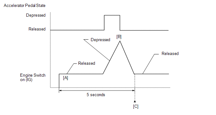
- Turn the engine switch on (IG) [A].
- Turn the Techstream on.
- Fully depress and release the accelerator pedal [B].
- Check that 5 seconds or more have elapsed since the engine switch is turned on (IG).
- Enter the following menus: Powertrain / Engine / Trouble Codes [C].
-
Read the pending DTCs.
HINT:
- If a pending DTC is output, the system is malfunctioning.
- If a pending DTC is not output, perform the following procedure.
- Enter the following menus: Powertrain / Engine / Utility / All Readiness.
- Input the DTC: P212012, P212014, P21201F, P212512, P212514, P21251F or P21382B.
-
Check the DTC judgment result.
Techstream Display
Description
NORMAL
- DTC judgment completed
- System normal
ABNORMAL
- DTC judgment completed
- System abnormal
INCOMPLETE
- DTC judgment not completed
- Perform driving pattern after confirming DTC enabling conditions
HINT:
- If the judgment result shows NORMAL, the system is normal.
- If the judgment result shows ABNORMAL, the system has a malfunction.
- If the judgment result is INCOMPLETE, perform steps [B] through [C] again.
-
[A] to [C]: Normal judgment procedure.
The normal judgment procedure is used to complete DTC judgment and also used when clearing permanent DTCs.
- When clearing the permanent DTCs, do not disconnect the cable from the battery terminal or attempt to clear the DTCs during this procedure, as doing so will clear the universal trip and normal judgment histories.
FAIL-SAFE
When DTC P212012, P212014, P21201C, P21201F, P212099, P212512, P212514, P21251F or P21382B is stored, the ECM enters fail-safe mode. If either of the 2 sensor circuits malfunctions, the ECM limits the engine output. If both of the circuits malfunction, the ECM regards the accelerator pedal as being released. As a result, the throttle valve is closed and the engine idles.
Fail-safe mode continues until a pass condition is detected, and the engine switch is turned off.
WIRING DIAGRAM
CAUTION / NOTICE / HINT
HINT:
Read freeze frame data using the Techstream. The ECM records vehicle and driving condition information as freeze frame data the moment a DTC is stored. When troubleshooting, freeze frame data can help determine if the vehicle was moving or stationary, if the engine was warmed up or not, if the air fuel ratio was lean or rich, and other data from the time the malfunction occurred.
PROCEDURE
| 1. | READ VALUE USING TECHSTREAM (ACCELERATOR PEDAL POSITION SENSOR) |
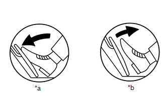
| *a | Fully Depressed |
| *b | Fully Released |
(a) Connect the Techstream to the DLC3.
(b) Turn the engine switch on (IG).
(c) Turn the Techstream on.
(d) Enter the following menus: Powertrain / Engine / Data List / Accelerator Position Sensor No.1 Voltage and Accelerator Position Sensor No.2 Voltage.
Powertrain > Engine > Data List| Tester Display |
|---|
| Accelerator Position Sensor No.1 Voltage |
| Accelerator Position Sensor No.2 Voltage |
(e) Read the value displayed on the Techstream.
Standard Voltage:
| Accelerator Pedal Operation | Accelerator Position Sensor No.1 Voltage | Accelerator Position Sensor No.2 Voltage | Difference between Accelerator Position Sensor No.1 Voltage and Accelerator Position Sensor No.2 Voltage |
|---|---|---|---|
| Fully Released | 0.5 to 1.1 V | 1.2 to 2.0 V | More than 0.02 V |
| Fully Depressed | 2.6 to 4.5 V | 3.4 to 4.75 V |
| OK | .gif) | CHECK FOR INTERMITTENT PROBLEMS |
|
.gif)
| 2. | CHECK HARNESS AND CONNECTOR (ACCELERATOR PEDAL SENSOR ASSEMBLY - ECM) |
(a) Disconnect the accelerator pedal sensor assembly connector.
(b) Disconnect the ECM connector.
(c) Measure the resistance according to the value(s) in the table below.
Standard Resistance:
| Tester Connection | Condition | Specified Condition |
|---|---|---|
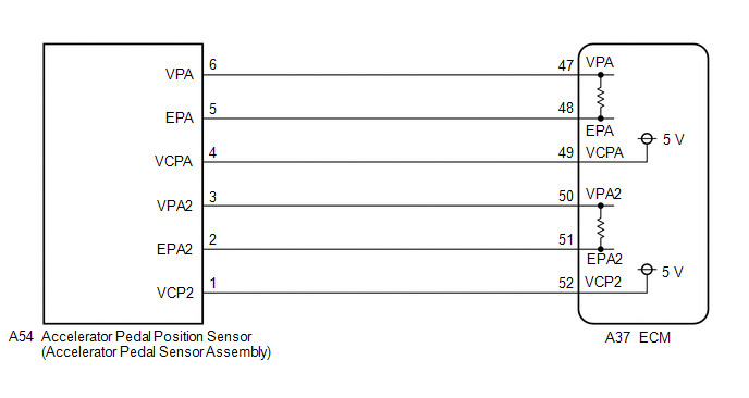
| A54-6 (VPA) - A37-47 (VPA) | Always | Below 1 Ω |
| A54-5 (EPA) - A37-48 (EPA) | Always | Below 1 Ω |
| A54-4 (VCPA) - A37-49 (VCPA) | Always | Below 1 Ω |
| A54-3 (VPA2) - A37-50 (VPA2) | Always | Below 1 Ω |
| A54-2 (EPA2) - A37-51 (EPA2) | Always | Below 1 Ω |
| A54-1 (VCP2) - A37-52 (VCP2) | Always | Below 1 Ω |
| A54-6 (VPA) or A37-47 (VPA) - Body ground and other terminals | Always | 10 kΩ or higher |
| A54-4 (VCPA) or A37-49 (VCPA) - Body ground and other terminals | Always | 10 kΩ or higher |
| A54-3 (VPA2) or A37-50 (VPA2) - Body ground and other terminals | Always | 10 kΩ or higher |
| A54-1 (VCP2) or A37-52 (VCP2) - Body ground and other terminals | Always | 10 kΩ or higher |
| NG | | REPAIR OR REPLACE HARNESS OR CONNECTOR |
|
| 3. | CHECK TERMINAL VOLTAGE (POWER SOURCE OF ACCELERATOR PEDAL SENSOR ASSEMBLY) |
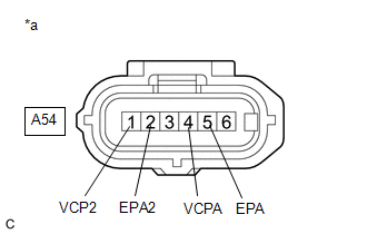
| *a | Front view of wire harness connector (to Accelerator Pedal Sensor Assembly) |
(a) Disconnect the accelerator pedal sensor assembly connector.
(b) Turn the engine switch on (IG).
(c) Measure the voltage according to the value(s) in the table below.
Standard Voltage:
| Tester Connection | Condition | Specified Condition |
|---|---|---|
| A54-4 (VCPA) - A54-5 (EPA) | Engine switch on (IG) | 4.5 to 5.5 V |
| A54-1 (VCP2) - A54-2 (EPA2) | Engine switch on (IG) | 4.5 to 5.5 V |
| NG | | REPLACE ECM |
|
| 4. | REPLACE ACCELERATOR PEDAL SENSOR ASSEMBLY |
(a) Replace the accelerator pedal sensor assembly.
Click here
|
| 5. | CHECK WHETHER DTC OUTPUT RECURS (ACCELERATOR PEDAL SENSOR DTCS) |
(a) Connect the Techstream to the DLC3.
(b) Turn the engine switch on (IG).
(c) Turn the Techstream on.
(d) Clear the DTCs.
Powertrain > Engine > Clear DTCs(e) Turn the engine switch off and wait for at least 30 seconds.
(f) Turn the engine switch on (IG).
(g) Turn the Techstream on.
(h) Drive the vehicle in accordance with the driving pattern described in Confirmation Driving Pattern.
(i) Enter the following menus: Powertrain / Engine / Trouble Codes.
(j) Read the DTCs.
| Result | Proceed to |
|---|---|
| DTCs are not output | A |
| DTC P212012, P212014, P21201F, P212512, P212514, P21251F, and/or P21382B are output | B |
| A | | END |
| B | | REPLACE ECM |
 Throttle Actuator "A" Control Throttle Body Range/Performance (P211900,P211904,P211977)
DESCRIPTION The electronic throttle control system is composed of the throttle actuator, throttle position sensor, accelerator pedal position sensor, and ECM. The ECM operates the throttle actuator to ...
 Throttle/Pedal Position Sensor/Switch "D" Circuit Voltage Out of Range (P21201C,P212099)
DESCRIPTION Refer to DTC P212012. Click here DTC No. Detection Item DTC Detection Condition Trouble Area MIL Memory Note P21201C Throttle/Pedal Position Sensor/Switch "D" Circui ...
Other materials:
Lexus RX (RX 350L, RX450h) 2016-2025 Repair Manual > Steering Gear: Removal
REMOVAL CAUTION / NOTICE / HINT The necessary procedures (adjustment, calibration, initialization, or registration) that must be performed after parts are removed and installed, or replaced during steering gear assembly removal/installation are shown below. Necessary Procedures After Parts Removed/I ...
Lexus RX (RX 350L, RX450h) 2016-2025 Repair Manual > Blind Spot Monitor Sensor: Components
COMPONENTS ILLUSTRATION *1 BLIND SPOT MONITOR SENSOR LH *2 BLIND SPOT MONITOR SENSOR RH N*m (kgf*cm, ft.*lbf): Specified torque - - ...
Lexus RX (RX 350L, RX450h) 2016-{YEAR} Owners Manual
- For your information
- Pictorial index
- For safety and security
- Instrument cluster
- Operation of each component
- Driving
- Lexus Display Audio system
- Interior features
- Maintenance and care
- When trouble arises
- Vehicle specifications
- For owners
Lexus RX (RX 350L, RX450h) 2016-{YEAR} Repair Manual

0.0166