Lexus RX (RX 350L, RX450h) 2016-2026 Repair Manual: Throttle/Pedal Position Sensor/Switch "D" Circuit Voltage Out of Range (P21201C,P212099)
DESCRIPTION
Refer to DTC P212012.
Click here .gif)
| DTC No. | Detection Item | DTC Detection Condition | Trouble Area | MIL | Memory | Note |
|---|---|---|---|---|---|---|
| P21201C | Throttle/Pedal Position Sensor/Switch "D" Circuit Voltage Out of Range | Difference between VPA and VPA2 is greater than or equal to the specified value for 0.5 seconds (1 trip detection logic). |
| Comes on | DTC stored | SAE Code: P2121 |
| P212099 | Throttle/Pedal Position Sensor/Switch "D" Exceeded Learning Limit | Difference between VPA and VPA2 is less than 0.4 V, or higher than 1.2 V (learned value of accelerator off position) (1 trip detection logic). |
| Comes on | DTC stored | SAE Code: P2121 |
MONITOR DESCRIPTION
The accelerator pedal position sensor is mounted on the accelerator pedal bracket. The accelerator pedal position sensor has 2 sensor elements and 2 signal outputs: VPA and VPA2. VPA is used to detect the actual accelerator pedal angle (used for engine control) and VPA2 is used to detect malfunctions in VPA. When the difference between the output voltages of VPA and VPA2 deviates from the standard, the ECM determines that the accelerator pedal position sensor is malfunctioning, illuminates the MIL and stores a DTC.
MONITOR STRATEGY
| Related DTCs | P2121: Accelerator pedal position sensor rationality |
| Required Sensors/Components (Main) | Accelerator pedal sensor assembly |
| Required Sensors/Components (Related) | - |
| Frequency of Operation | Continuous |
| Duration | -: Case 1 0.5 seconds: Case 2 |
| MIL Operation | Immediate |
| Sequence of Operation | None |
TYPICAL ENABLING CONDITIONS
| Monitor runs whenever the following DTCs are not stored | None |
| Accelerator pedal position sensor circuit fail (P2120, P2122, P2123, P2125, P2127, P2128, P2138) | Not detected |
TYPICAL MALFUNCTION THRESHOLDS
Case 1| Difference between VPA voltage and VPA2 voltage (learned value of accelerator off position) | Less than 0.4 V, or higher than 1.2 V |
| All of the following conditions are met | - |
| [(VPA voltage - Learned VPA accelerator off position voltage) - (VPA2 voltage - Learned VPA2 accelerator off position voltage)] | 0.165 V or higher (varies with accelerator position) |
| VPA2 voltage | Less than 4.84 V |
| Either of following conditions met: | (a) or (b) |
| (a) VPA voltage - Learned VPA accelerator off position voltage | 0.04 V or higher |
| (b) VPA2 voltage - Learned VPA2 accelerator off position voltage | 0.04 V or higher |
CONFIRMATION DRIVING PATTERN
HINT:
-
After repair has been completed, clear the DTC and then check that the vehicle has returned to normal by performing the following All Readiness check procedure.
Click here
-
When clearing the permanent DTCs, refer to the "CLEAR PERMANENT DTC" procedure.
Click here
- Connect the Techstream to the DLC3.
- Turn the engine switch on (IG).
- Turn the Techstream on.
- Clear the DTCs (even if no DTCs are stored, perform the clear DTC procedure).
- Turn the engine switch off and wait for at least 30 seconds.
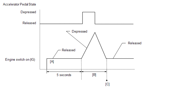
- Turn the engine switch on (IG) [A].
- Turn the Techstream on.
- Wait for 5 seconds after turning the engine switch on (IG).
-
Operate the accelerator pedal in accordance with the following procedure [B].
- Enter the following menus: Powertrain / Engine / Data List / Accelerator Position Sensor No.1 Voltage % and Accelerator Position Sensor No.2 Voltage %.
- Slowly depress the accelerator pedal until Accelerator Position Sensor No.1 Voltage % is approximately 30% and Accelerator Position Sensor No.2 Voltage % is approximately 46%, then slowly release the accelerator pedal.
- Enter the following menus: Powertrain / Engine / Trouble Codes [C].
-
Read the pending DTCs.
HINT:
- If a pending DTC is output, the system is malfunctioning.
- If a pending DTC is not output, perform the following procedure.
- Enter the following menus: Powertrain / Engine / Utility / All Readiness.
- Input the DTC: P21201C or P212099.
-
Check the DTC judgment result.
Techstream Display
Description
NORMAL
- DTC judgment completed
- System normal
ABNORMAL
- DTC judgment completed
- System abnormal
INCOMPLETE
- DTC judgment not completed
- Perform driving pattern after confirming DTC enabling conditions
HINT:
- If the judgment result shows NORMAL, the system is normal.
- If the judgment result is ABNORMAL, the system is malfunctioning.
- If the judgment result is INCOMPLETE, perform steps [B] through [C] again.
-
[A] to [C]: Normal judgment procedure.
The normal judgment procedure is used to complete DTC judgment and also used when clearing permanent DTCs.
- When clearing the permanent DTCs, do not disconnect the cable from the battery terminal or attempt to clear the DTCs during this procedure, as doing so will clear the universal trip and normal judgment histories.
FAIL-SAFE
When DTC P212012, P212014, P21201C, P21201F, P212099, P212512, P212514, P21251F or P21382B is stored, the ECM enters fail-safe mode. If either of the 2 sensor circuits malfunctions, the ECM limits the engine output. If both of the circuits malfunction, the ECM regards the accelerator pedal as being released. As a result, the throttle valve is closed and the engine idles.
If a pass condition is detected and then the engine switch is turned off, the fail-safe operation stops and the system returns to normal.
WIRING DIAGRAM
Refer to DTC P212012.
Click here
CAUTION / NOTICE / HINT
HINT:
Read freeze frame data using the Techstream. The ECM records vehicle and driving condition information as freeze frame data the moment a DTC is stored. When troubleshooting, freeze frame data can help determine if the vehicle was moving or stationary, if the engine was warmed up or not, if the air fuel ratio was lean or rich, and other data from the time the malfunction occurred.
PROCEDURE
| 1. | CHECK ANY OTHER DTCS OUTPUT (IN ADDITION TO DTC P21201C AND/OR P212099) |
(a) Connect the Techstream to the DLC3.
(b) Turn the engine switch on (IG).
(c) Turn the Techstream on.
(d) Enter the following menus: Powertrain / Engine / Trouble Codes.
(e) Read the DTCs.
Powertrain > Engine > Trouble Codes| Result | Proceed to |
|---|---|
| DTC P21201C and/or P212099 are output | A |
| DTC P21201C and/or P212099 and other DTCs are output | B |
HINT:
If any DTCs other than P21201C and/or P212099 are output, troubleshoot those DTCs first.
| B | .gif) | GO TO DTC CHART |
|
.gif)
| 2. | READ VALUE USING TECHSTREAM (ACCELERATOR PEDAL POSITION SENSOR) |
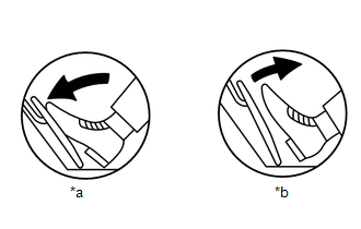
| *a | Fully Depressed |
| *b | Fully Released |
(a) Connect the Techstream to the DLC3.
(b) Turn the engine switch on (IG).
(c) Turn the Techstream on.
(d) Enter the following menus: Powertrain / Engine / Data List / Accelerator Position Sensor No.1 Voltage and Accelerator Position Sensor No.2 Voltage.
Powertrain > Engine > Data List| Tester Display |
|---|
| Accelerator Position Sensor No.1 Voltage |
| Accelerator Position Sensor No.2 Voltage |
(e) Read the values displayed on the Techstream.
Standard Voltage:
| Accelerator Pedal Operation | Accelerator Position Sensor No.1 Voltage | Accelerator Position Sensor No.2 Voltage |
|---|---|---|
| Fully Released | 0.5 to 1.1 V | 1.2 to 2.0 V |
| Fully Depressed | 2.6 to 4.5 V | 3.4 to 4.75 V |
| OK | | CHECK FOR INTERMITTENT PROBLEMS |
|
| 3. | REPLACE ACCELERATOR PEDAL(W/SENSOR) ROD ASSEMBLY |
(a) Replace the accelerator pedal sensor assembly.
Click here
|
| 4. | CHECK WHETHER DTC OUTPUT RECURS (DTC P21201C AND/OR P212099) |
(a) Connect the Techstream to the DLC3.
(b) Turn the engine switch on (IG).
(c) Turn the Techstream on.
(d) Clear the DTCs.
Powertrain > Engine > Clear DTCs(e) Turn the engine switch off and wait for at least 30 seconds.
(f) Turn the engine switch on (IG).
(g) Turn the Techstream on.
(h) Drive the vehicle in accordance with the driving pattern described in Confirmation Driving Pattern.
(i) Enter the following menus: Powertrain / Engine / Trouble Codes.
(j) Read the DTCs.
Powertrain > Engine > Trouble Codes| Result | Proceed to |
|---|---|
| DTCs are not output | A |
| DTC P21201C and/or P212099 are output | B |
| A | | END |
| B | | REPLACE ECM |
 Throttle/Pedal Position Sensor/Switch "D" Circuit Short to Battery (P212012,P212014,P21201F,P212512,P212514,P21251F,P21382B)
DESCRIPTION HINT:
This Electronic Throttle Control System (ETCS) does not use a throttle cable.
These DTCs relate to the accelerator pedal position sensor.
The accelerator pedal position senso ...
 A/F (O2) Sensor Signal Biased/Stuck Lean Bank 1 Sensor 1 Circuit Current Above Threshold (P219519,P219524,P219618,P219623,P219719,P219724,P219818,P219823)
DESCRIPTION HINT: Although the DTC titles say oxygen sensor, these DTCs relate to the air fuel ratio sensor. The air fuel ratio sensor generates voltage* that corresponds to the actual air fuel ratio. ...
Other materials:
Lexus RX (RX 350L, RX450h) 2016-2026 Repair Manual > Headlight Assembly: Repair
REPAIR CAUTION / NOTICE / HINT HINT:
Use the same procedure for the RH side and LH side.
The following procedure is for the LH side.
If the installation area of the headlight assembly is damaged, use a supply retainer for a low-cost repair.
Ensure that the headlight assembly is not damaged. ...
Lexus RX (RX 350L, RX450h) 2016-2026 Repair Manual > Air Conditioning Pressure Sensor: On-vehicle Inspection
ON-VEHICLE INSPECTION PROCEDURE 1. INSPECT AIR CONDITIONER PRESSURE SENSOR (a) Check the wire harness. (1) Disconnect the A9 air conditioner pressure sensor connector. (2) Disconnect the J42 air conditioning amplifier assembly connector. (3) Measure the resistance according to the value(s) in the ta ...
Lexus RX (RX 350L, RX450h) 2016-{YEAR} Owners Manual
- For your information
- Pictorial index
- For safety and security
- Instrument cluster
- Operation of each component
- Driving
- Lexus Display Audio system
- Interior features
- Maintenance and care
- When trouble arises
- Vehicle specifications
- For owners
Lexus RX (RX 350L, RX450h) 2016-{YEAR} Repair Manual

0.0111