Lexus RX (RX 350L, RX450h) 2016-2026 Repair Manual: Fuel Pump Control Circuit
DESCRIPTION
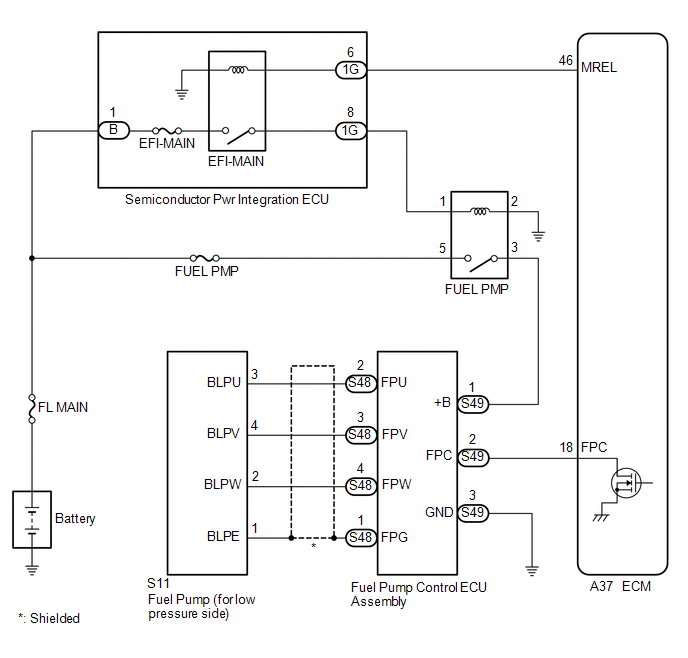
The fuel pump (for low pressure side) circuit consists of the ECM, fuel pump (for low pressure side) and fuel pump control ECU assembly (which operates the fuel pump (for low pressure side)). Based on the engine output, the ECM determines the fuel pump speed. The speed is then converted to a duty signal and sent to the fuel pump control ECU assembly. Based on the signal sent from the ECM, the fuel pump control ECU assembly adjusts the fuel pump (for low pressure side) operation speed.
WIRING DIAGRAM
CAUTION / NOTICE / HINT
NOTICE:
Inspect the fuses for circuits related to this system before performing the following procedure.
PROCEDURE
| 1. | CHECK FUEL LEAK |
(a) Check around and beneath the vehicle for fuel leaks, fumes, etc.
OK:
No fuel leaks present.
| NG | .gif) | REPAIR OR REPLACE FUEL LEAK POINT |
|
.gif)
| 2. | PERFORM ACTIVE TEST USING TECHSTREAM (ACTIVATE THE CIRCUIT RELAY) |
(a) Connect the Techstream to the DLC3.
(b) Turn the engine switch on (IG).
(c) Turn the Techstream on.
(d) Enter the following menus: Powertrain / Engine / Active Test / Activate the Circuit Relay.
Powertrain > Engine > Active Test| Tester Display |
|---|
| Activate the Circuit Relay |
Standard:
| Techstream Operation | Standard |
|---|---|
| ON | Operating sounds can be heard from fuel pump (for low pressure side) |
| NG | | GO TO STEP 7 |
|
| 3. | PERFORM ACTIVE TEST USING TECHSTREAM (CONTROL THE FUEL PUMP DUTY RATIO) |
(a) Install the fuel pressure gauge (for low pressure line of low pressure side).
Click here .gif)
(b) Connect the Techstream to the DLC3.
(c) Turn the engine switch on (IG).
(d) Turn the Techstream on.
(e) Enter the following menus: Powertrain / Engine / Active Test / Control the Fuel Pump Duty Ratio / Data List / Fuel Pressure (Low) / Fuel Pressure 2.
Powertrain > Engine > Active Test| Active Test Display |
|---|
| Control the Fuel Pump Duty Ratio |
| Data List Display |
|---|
| Fuel Pressure (Low) / Fuel Pressure 2 |
Standard:
| Techstream Operation | Standard |
|---|---|
| Low | Data List value and fuel pressure gauge are within +/-50 kPag of each other |
| High |
HINT:
Perform "Inspection After Repair" after replacing the fuel pressure sensor (for low pressure side).
Click here
| NG | | REPLACE FUEL DELIVERY PIPE SUB-ASSEMBLY (FUEL PRESSURE SENSOR (FOR LOW PRESSURE SIDE)) |
|
| 4. | READ VALUE USING TECHSTREAM (FUEL PRESSURE) |
(a) Connect the Techstream to the DLC3.
(b) Turn the engine switch on (IG).
(c) Turn the Techstream on.
(d) Enter the following menus: Powertrain / Engine / Data List / Target Fuel Pressure (Low) / Target Fuel Pressure 2, Fuel Pressure (Low) / Fuel Pressure 2 and Low Fuel Pressure Sensor.
Powertrain > Engine > Data List| Tester Display |
|---|
| Target Fuel Pressure (Low) / Target Fuel Pressure 2 |
| Fuel Pressure (Low) / Fuel Pressure 2 |
| Low Fuel Pressure Sensor |
| Result | Proceed to |
|---|---|
| Low Fuel Pressure Sensor value is within +/- 65 kPag of the Target Fuel Pressure (Low) / Target Fuel Pressure 2 | A |
| Low Fuel Pressure Sensor value is more than 65 kPag higher than the Target Fuel Pressure (Low) / Target Fuel Pressure 2 | B |
| Low Fuel Pressure Sensor value is more than 65 kPag lower than the Target Fuel Pressure (Low) / Target Fuel Pressure 2 | C |
| B | | REPLACE FUEL PUMP (FOR LOW PRESSURE SIDE) |
| C | | GO TO STEP 6 |
|
| 5. | CHECK FUEL PRESSURE |
(a) Install the fuel pressure gauge (for low pressure line of low pressure side).
Click here
(b) Start the engine.
(c) Measure the fuel pressure at idle.
Standard Fuel Pressure:
196 to 833 kPa (2.0 to 8.5 kgf/cm2, 28 to 121 psi)
HINT:
Refer to Standard Idle Speed.
Click here
(d) Stop the engine.
(e) Check that the fuel pressure remains as specified for 5 minutes.
Standard Fuel Pressure:
98 kPa (1.0 kgf/cm2, 14 psi) or more
HINT:
Perform "Inspection After Repair" after replacing the fuel pump (for low pressure side).
Click here
| OK | | PROCEED TO NEXT SUSPECTED AREA SHOWN IN PROBLEM SYMPTOMS TABLE |
| NG | | REPLACE FUEL PUMP (FOR LOW PRESSURE SIDE) |
| 6. | CHECK SHORTAGE OF FUEL |
(a) Check the amount of fuel remaining.
HINT:
- No fuel remains in the fuel tank: Malfunction of the fuel sender gauge assembly is suspected.
- Only the fuel pump side fuel chamber has no fuel remaining: Malfunction of the jet pump is suspected.
- Fuel remains in the fuel tank: Malfunction of the fuel pump (for low pressure side) is suspected.
-
Perform "Inspection After Repair" after replacing the fuel pump (for low pressure side).
Click here
| NEXT | | REPLACE FUEL PUMP (FOR LOW PRESSURE SIDE) |
| 7. | PERFORM ACTIVE TEST USING TECHSTREAM (FUEL PUMP SINGLE PHASE ENERGIZATION) |
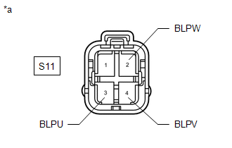
| *a | Front view of wire harness connector (to Fuel Pump (for low pressure side)) |
(a) Disconnect the fuel pump (for low pressure side) connector.
(b) Connect the Techstream to the DLC3.
(c) Turn the engine switch on (IG).
(d) Turn the Techstream on.
(e) Enter the following menus: Powertrain / Engine / Active Test / Fuel Pump Single Phase Energization.
Powertrain > Engine > Active Test| Tester Display |
|---|
| Fuel Pump Single Phase Energization |
(f) Operate the fuel pump control ECU assembly using the Active Test function and measure the voltage according to the value(s) in the table below.
Standard Voltage:
| Tester Connection | GTS Operation | Specified Condition |
|---|---|---|
| S11-3 (BLPU) - Body ground | U Phase | 4.4 to 8.4 V* |
| S11-4 (BLPV) - Body ground | V Phase | 4.4 to 8.4 V* |
| S11-2 (BLPW) - Body ground | W Phase | 4.4 to 8.4 V* |
HINT:
- *: This Active Test restricts the fuel pump control ECU assembly output duty cycle to 50%. Therefore, the output voltage of the fuel pump control ECU assembly will be approximately 50% of the power source voltage.
- Before performing this inspection, check that the battery voltage is between 11 and 14 V (not depleted).
-
Perform "Inspection After Repair" after replacing the fuel pump (for low pressure side).
Click here
| OK | | REPLACE FUEL PUMP (FOR LOW PRESSURE SIDE) |
|
| 8. | CHECK HARNESS AND CONNECTOR (FUEL PUMP CONTROL ECU ASSEMBLY - FUEL PUMP (FOR LOW PRESSURE SIDE)) |
(a) Disconnect the fuel pump control ECU assembly connector.
(b) Disconnect the fuel pump (for low pressure side) connector.
(c) Measure the resistance according to the value(s) in the table below.
Standard Resistance:
| Tester Connection | Condition | Specified Condition |
|---|---|---|
| S48-2 (FPU) - S11-3 (BLPU) | Always | Below 1 Ω |
| S48-3 (FPV) - S11-4 (BLPV) | Always | Below 1 Ω |
| S48-4 (FPW) - S11-2 (BLPW) | Always | Below 1 Ω |
| S48-2 (FPU) or S11-3 (BLPU) - Body ground and other terminals | Always | 10 kΩ or higher |
| S48-3 (FPV) or S11-4 (BLPV) - Body ground and other terminals | Always | 10 kΩ or higher |
| S48-4 (FPW) or S11-2 (BLPW) - Body ground and other terminals | Always | 10 kΩ or higher |
| NG | | REPAIR OR REPLACE HARNESS OR CONNECTOR |
|
| 9. | CHECK HARNESS AND CONNECTOR (POWER SOURCE OF FUEL PUMP CONTROL ECU ASSEMBLY) |
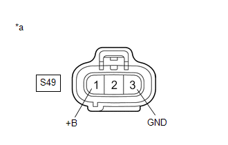
| *a | Front view of wire harness connector (to Fuel Pump Control ECU Assembly) |
(a) Disconnect the fuel pump control ECU assembly connector.
(b) Turn the engine switch on (IG).
(c) Measure the voltage according to the value(s) in the table below.
Standard Voltage:
| Tester Connection | Condition | Specified Condition |
|---|---|---|
| S49-1 (+B) - S49-3 (GND) | Engine switch on (IG) | 11 to 14 V |
HINT:
Make a note of the measured voltage as it may be used in a following Active Test.
| NG | | GO TO STEP 12 |
|
| 10. | INSPECT ECM (FPC TERMINAL) |
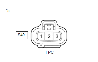
| *a | Front view of wire harness connector (to Fuel Pump Control ECU Assembly) |
(a) Disconnect the fuel pump control ECU assembly connector.
(b) Connect the Techstream to the DLC3.
(c) Turn the engine switch on (IG).
(d) Turn the Techstream on.
(e) Enter the following menus: Powertrain / Engine / Active Test / Fuel Pump Single Phase Energization.
Powertrain > Engine > Active Test| Tester Display |
|---|
| Fuel Pump Single Phase Energization |
(f) Operate the fuel pump control ECU assembly using the Active Test function and measure the resistance according to the value(s) in the table below.
Standard Resistance:
| Tester Connection | Techstream Operation | Specified Condition |
|---|---|---|
| S49-2 (FPC) - Body ground | Before Active Test → During Active Test | Before Active Test: Resistance is stable → During Active Test: Resistance fluctuates* |
HINT:
*: Using the Active Test, duty control of the transistors in the ECM will be performed. Due to the duty control, resistance of the FPC terminal will be unstable during the Active Test. If the resistance is stable before the Active Test and fluctuates while performing the Active Test, it can be determined that the transistor is operating. If the transistor does not operate during the Active Test, the ECM may be malfunctioning.
| OK | | REPLACE FUEL PUMP CONTROL ECU ASSEMBLY |
|
| 11. | CHECK HARNESS AND CONNECTOR (FUEL PUMP CONTROL ECU ASSEMBLY - ECM) |
(a) Disconnect the fuel pump control ECU assembly connector.
(b) Disconnect the ECM connector.
(c) Measure the resistance according to the value(s) in the table below.
Standard Resistance:
| Tester Connection | Condition | Specified Condition |
|---|---|---|
| S49-2 (FPC) - A37-18 (FPC) | Always | Below 1 Ω |
| S49-2 (FPC) or A37-18 (FPC) - Body ground and other terminals | Always | 10 kΩ or higher |
| OK | | REPLACE ECM |
| NG | | REPAIR OR REPLACE HARNESS OR CONNECTOR |
| 12. | CHECK HARNESS AND CONNECTOR (FUEL PUMP CONTROL ECU ASSEMBLY - BODY GROUND) |
(a) Disconnect the fuel pump control ECU assembly connector.
(b) Measure the resistance according to the value(s) in the table below.
Standard Resistance:
| Tester Connection | Condition | Specified Condition |
|---|---|---|
| S49-3 (GND) - Body ground | Always | Below 1 Ω |
| NG | | REPAIR OR REPLACE HARNESS OR CONNECTOR |
|
| 13. | CHECK HARNESS AND CONNECTOR (POWER SOURCE VOLTAGE OF FUEL PMP RELAY) |
(a) Remove the FUEL PMP relay from the engine room relay block and junction block assembly.
(b) Measure the voltage according to the value(s) in the table below.
Standard Voltage:
| Tester Connection | Condition | Specified Condition |
|---|---|---|
| 5 (FUEL PMP relay) - Body ground | Always | 11 to 14 V |
| NG | | REPAIR OR REPLACE HARNESS OR CONNECTOR (BATTERY - FUEL PMP RELAY) |
|
| 14. | INSPECT FUEL PMP RELAY |
(a) Inspect the FUEL PMP relay.
Click here
| NG | | REPLACE FUEL PMP RELAY |
|
| 15. | CHECK HARNESS AND CONNECTOR (SEMICONDUCTOR PWR INTEGRATION ECU - ECM) |
(a) Disconnect the semiconductor pwr integration ECU connector.
(b) Disconnect the ECM connector.
(c) Measure the resistance according to the value(s) in the table below.
Standard Resistance:
| Tester Connection | Condition | Specified Condition |
|---|---|---|
| 1G-6 - A37-46 (MREL) | Always | Below 1 Ω |
| 1G-6 or A37-46 (MREL) - Body ground and other terminals | Always | 10 kΩ or higher |
| NG | | REPAIR OR REPLACE HARNESS OR CONNECTOR |
|
| 16. | CHECK HARNESS AND CONNECTOR (SEMICONDUCTOR PWR INTEGRATION ECU - FUEL PMP RELAY) |
(a) Remove the FUEL PMP relay from the engine room relay block and junction block assembly.
(b) Disconnect the semiconductor pwr integration ECU connector.
(c) Measure the resistance according to the value(s) in the table below.
Standard Resistance:
| Tester Connection | Condition | Specified Condition |
|---|---|---|
| 1G-8 - 1 (FUEL PMP relay) | Always | Below 1 Ω |
| 1G-8 or 1 (FUEL PMP relay) - Body ground and other terminals | Always | 10 kΩ or higher |
| NG | | REPAIR OR REPLACE HARNESS OR CONNECTOR |
|
| 17. | CHECK HARNESS AND CONNECTOR (FUEL PMP RELAY - BODY GROUND) |
(a) Remove the FUEL PMP relay from the engine room relay block and junction block assembly.
(b) Measure the resistance according to the value(s) in the table below.
Standard Resistance:
| Tester Connection | Condition | Specified Condition |
|---|---|---|
| 2 (FUEL PMP relay) - Body ground | Always | Below 1 Ω |
| NG | | REPAIR OR REPLACE HARNESS OR CONNECTOR |
|
| 18. | CHECK HARNESS AND CONNECTOR (FUEL PMP RELAY - FUEL PUMP CONTROL ECU ASSEMBLY) |
(a) Remove the FUEL PMP relay from the engine room relay block and junction block assembly.
(b) Disconnect the fuel pump control ECU assembly connector.
(c) Measure the resistance according to the value(s) in the table below.
Standard Resistance:
| Tester Connection | Condition | Specified Condition |
|---|---|---|
| 3 (FUEL PMP relay) - S49-1 (+B) | Always | Below 1 Ω |
| 3 (FUEL PMP relay) or S49-1 (+B) - Body ground and other terminals | Always | 10 kΩ or higher |
| OK | | GO TO ECM POWER SOURCE CIRCUIT |
| NG | | REPAIR OR REPLACE HARNESS OR CONNECTOR |
 EVAP System
RELATED DTCS DTC No. SAE Monitoring Item Link P00FE00 P00FE EVAP vent line blocked P043E00 P043E Reference orifice clogged (built into canister pump module) P043 ...
 Starter Signal Circuit
DESCRIPTION While the engine is being cranked, current flows from terminal STAR of the certification ECU (smart key ECU assembly) to the park/neutral position switch assembly and to terminal STA of th ...
Other materials:
Lexus RX (RX 350L, RX450h) 2016-2026 Repair Manual > Rear No. 1 Seat Assembly (for 60/40 Split Seat Type Lh Side): Reassembly
REASSEMBLY CAUTION / NOTICE / HINT CAUTION: Wear protective gloves. Sharp areas on the seat frame may injure your hands. PROCEDURE 1. INSTALL REAR SEATBACK FRAME SUB-ASSEMBLY LH (a) Temporarily install the rear seatback frame sub-assembly LH to the No. 1 seat cushion frame sub-assembly LH as shown i ...
Lexus RX (RX 350L, RX450h) 2016-2026 Repair Manual > Can Communication System: Parts Location
PARTS LOCATION ILLUSTRATION *1 MILLIMETER WAVE RADAR SENSOR ASSEMBLY *2 SKID CONTROL ECU (BRAKE ACTUATOR ASSEMBLY) *3 ECM *4 FORWARD RECOGNITION CAMERA *5 HEADLIGHT ECU SUB-ASSEMBLY LH (w/ Automatic Headlight Beam Level Control System) *6 ABSORBER CONTROL ECU (w/ AVS) ...
Lexus RX (RX 350L, RX450h) 2016-{YEAR} Owners Manual
- For your information
- Pictorial index
- For safety and security
- Instrument cluster
- Operation of each component
- Driving
- Lexus Display Audio system
- Interior features
- Maintenance and care
- When trouble arises
- Vehicle specifications
- For owners
Lexus RX (RX 350L, RX450h) 2016-{YEAR} Repair Manual

0.0143