Lexus RX (RX 350L, RX450h) 2016-2026 Repair Manual: Reassembly
REASSEMBLY
CAUTION / NOTICE / HINT
CAUTION:
Wear protective gloves. Sharp areas on the seat frame may injure your hands.
PROCEDURE
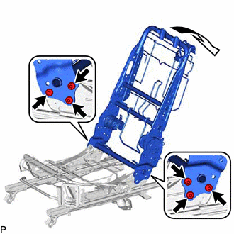
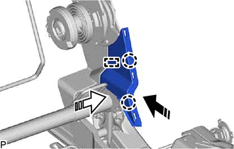
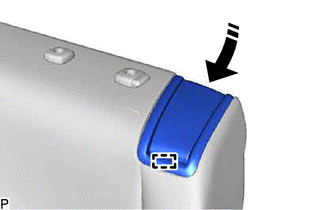
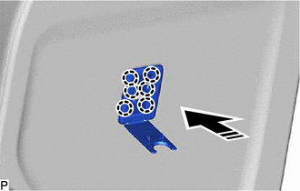
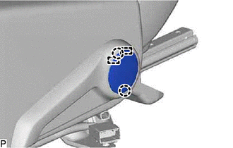
1. INSTALL REAR SEATBACK FRAME SUB-ASSEMBLY LH
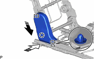
(a) Temporarily install the rear seatback frame sub-assembly LH to the No. 1 seat cushion frame sub-assembly LH as shown in the illustration.
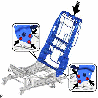
.png) | Install in this Direction |
(b) Using a T40 "TORX" socket wrench, temporarily install the 6 bolts.
| (c) Using a T40 "TORX" socket wrench, tighten the 6 bolts while pulling the rear seatback frame sub-assembly LH as shown in the illustration. Torque: 29 N·m {296 kgf·cm, 21 ft·lbf} |
|
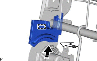
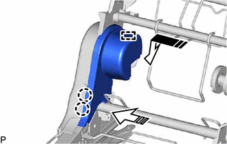
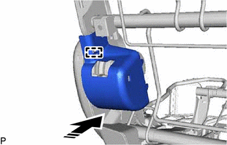
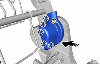
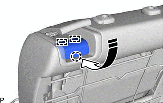
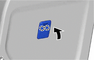
2. INSTALL RECLINING CONTROL LINK SUB-ASSEMBLY LH
| (a) Install the reclining control link sub-assembly LH with the 2 nuts. Torque: 21 N·m {214 kgf·cm, 15 ft·lbf} |
|
.png)
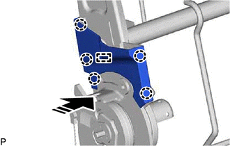
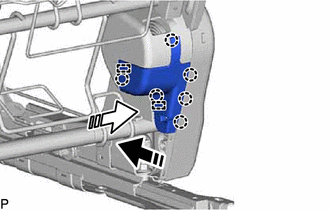
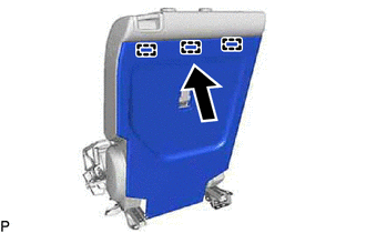
3. INSTALL RECLINING CONTROL LINK SUB-ASSEMBLY LH
| (a) Install the reclining control link sub-assembly LH with the 2 nuts. Torque: 21 N·m {214 kgf·cm, 15 ft·lbf} |
|
.png)
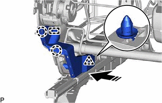
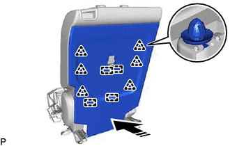
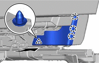
4. INSTALL REAR SEAT RECLINING CONTROL CABLE
(a) Route the rear seat reclining control cable as shown in the illustration and engage the clip and clamp.
.png)
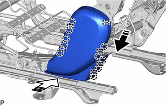
(b) Engage the 8 clamps to install the rear seat reclining control cable.
.png)
5. INSTALL REAR NO. 1 SEAT TRACK CONTROL CABLE ASSEMBLY LH
(a) Route the rear No. 1 seat track control cable assembly LH as shown in the illustration and engage the clamp.
.png)
(b) Engage the 6 clamps to install the rear No. 1 seat track control cable assembly LH.
.png)
6. INSTALL RECLINING ADJUSTING CABLE ASSEMBLY
(a) Route the reclining adjusting cable assembly as shown in the illustration and engage the 2 clamps.
.png)
(b) Engage the 6 clamps to install the reclining adjusting cable assembly.
.png)
7. INSTALL REAR SEAT WIRE LH
| (a) Engage the 5 clamps and 2 claws to install the rear seat wire LH. |
|
.png)
8. INSTALL REAR SEAT RECLINING SEAT COVER LH
(a) Engage the guide as shown in the illustration to install the rear seat reclining seat cover LH.
| | Install in this Direction (1) |
.png) | Install in this Direction (2) |
9. INSTALL REAR SEAT RECLINING SEAT COVER LH
(a) Engage the guide and 5 claws to install the rear seat reclining seat cover LH as shown in the illustration.
| | Install in this Direction |
10. INSTALL REAR SEAT INNER RECLINING COVER LH
(a) Engage the 2 guides, claw and clip as indicated by the arrows, in the order shown in the illustration to install the rear seat inner reclining cover LH.
| | Install in this Direction (1) |
| | Install in this Direction (2) |
11. INSTALL REAR NO. 1 SEAT RECLINING ADJUSTER INSIDE COVER
(a) Engage the guide and 2 claws as indicated by the arrows, in the order shown in the illustration to install the rear No. 1 seat reclining adjuster inside cover.
| | Install in this Direction (1) |
| | Install in this Direction (2) |
12. INSTALL REAR NO. 1 SEAT RECLINING ADJUSTER INSIDE COVER
(a) Engage the 2 guides and 6 claws as indicated by the arrows, in the order shown in the illustration to install the rear No. 1 seat reclining adjuster inside cover.
| | Install in this Direction (1) |
| | Install in this Direction (2) |
13. INSTALL REAR NO. 1 SEAT RECLINING ADJUSTER INSIDE COVER
(a) Engage the guide, 2 claws and clip to install the rear No. 1 seat reclining adjuster inside cover as shown in the illustration.
| | Install in this Direction |
14. INSTALL REAR NO. 1 SEAT RECLINING ADJUSTER INSIDE COVER
(a) Engage the guide and 2 claws as indicated by the arrows, in the order shown in the illustration to install the rear No. 1 seat reclining adjuster inside cover.
| | Install in this Direction (1) |
| | Install in this Direction (2) |
15. INSTALL REAR NO. 1 SEAT RECLINING COVER LH
(a) Engage the 6 guides and 10 claws as indicated by the arrows, in the order shown in the illustration to install the rear No. 1 seat reclining cover LH.
| | Install in this Direction (1) |
| | Install in this Direction (2) |
16. INSTALL NO. 2 RECLINING LINK COVER LH
(a) Engage the guide to install the No. 2 reclining link cover LH as shown in the illustration.
| | Install in this Direction |
17. INSTALL NO. 1 RECLINING LINK COVER LH
(a) Engage the guide and 5 claws to install the No. 1 reclining link cover LH as shown in the illustration.
| | Install in this Direction |
18. INSTALL REAR SEATBACK EDGE PROTECTOR
| (a) Install a new rear seatback edge protector. |
|
.png)
19. INSTALL REAR SEAT AIRBAG ASSEMBLY LH
Click here .gif)
20. INSTALL SEAT HEATER ASSEMBLY (w/ Seat Heater System)
Click here
21. INSTALL SEAT COVER WIRE
(a) Install the 5 seat cover wires.
HINT:
- Wire 1000 mm (3.28 ft.) or longer and shaped wires are available as supplied parts.
- For wires 1000 mm (3.28 ft.) or less in length, cut or shape a 1000 mm (3.28 ft.) wire into the dimensions shown in the illustration.
-
Make sure to read Precaution before preparing the wire.
Click here
Length:
| A | 110 mm (4.33 in.) |
| B | 330 mm (1.0824 ft.) |
| C | 200 mm (7.87 in.) |
HINT:
The dimension shown in the illustration is the length.
.png)
22. INSTALL RECLINING REMOTE CONTROL BEZEL LH
| (a) Install the reclining remote control bezel LH. |
|
.png)
23. INSTALL SEPARATE TYPE REAR SEATBACK COVER
HINT:
When installing a separate type rear seatback cover, refer to Precaution in order to prevent wrinkles from forming.
Click here
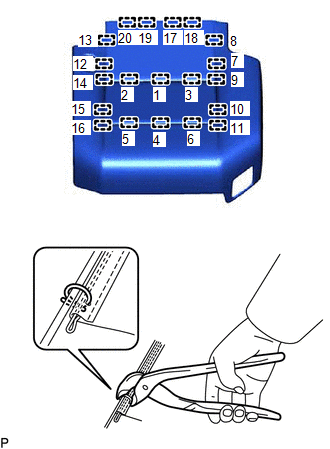
| (a) Using hog ring pliers, install 11 new hog rings in the order shown in the illustration. NOTICE:
|
|
| (b) Using hog ring pliers, install the separate type rear seatback cover to the separate type rear seatback pad with 2 new hog rings in the order shown in the illustration. NOTICE:
|
|
(c) Engage the 2 fasteners.
.png)
.png) | Fastener |
24. INSTALL SEPARATE TYPE REAR SEATBACK COVER WITH PAD
(a) Temporarily install the separate type rear seatback cover with pad to the rear seatback frame sub-assembly LH.
| (b) Install the 2 rear seatback cover brackets with the nut. Torque: 5.5 N·m {56 kgf·cm, 49 in·lbf} NOTICE:
|
|
.png)
(c) Engage the 4 claws to install the 2 rear No. 1 seat headrest support assemblies as shown in the illustration.
| | Install in this Direction |
| (d) Engage the 12 hooks to install the separate type rear seatback cover with pad. |
|
.png)
25. INSTALL RECLINING REMOTE CONTROL LEVER SUB-ASSEMBLY LH
| (a) Connect the reclining adjusting cable assembly. |
|
.png)
(b) Engage the guide as shown in the illustration.
| | Install in this Direction |
| (c) Install the reclining remote control lever sub-assembly LH with the 2 screws. |
|
.png)
26. INSTALL REAR SEAT UPPER RECLINING COVER LH
(a) Engage the 2 guides and claw to install the rear seat upper reclining cover LH as shown in the illustration.
| | Install in this Direction |
27. INSTALL NO. 2 SEAT CUSHION COVER SUB-ASSEMBLY LH
| (a) Engage the 2 guides to connect the rubber band and install the No. 2 seat cushion cover sub-assembly LH. |
|
.png)
28. INSTALL REAR SEATBACK BOARD CARPET ASSEMBLY LH
| (a) Engage the 3 guides as shown in the illustration. |
|
(b) Engage the 4 guides and 6 clips to install the rear seatback board carpet assembly LH as shown in the illustration.
| | Install in this Direction |
29. INSTALL REAR SEATBACK COVER LH
(a) Engage the 6 claws to install the rear seatback cover LH as shown in the illustration.
| | Install in this Direction |
| (b) Engage the 2 claws as shown in the illustration. |
|
30. INSTALL REAR SEAT INNER BELT ASSEMBLY LH
Click here
31. INSTALL REAR NO. 1 SEAT RECLINING ADJUSTER INSIDE COVER
(a) Engage the 3 claws and clip to install the rear No. 1 seat reclining adjuster inside cover as shown in the illustration.
| | Install in this Direction |
32. INSTALL SEAT HEATER CONTROL SUB-ASSEMBLY LH (w/ Seat Heater System)
| (a) Engage the 2 clamps to install the seat heater control sub-assembly LH. |
|
.png)
(b) Connect the connector.
33. INSTALL REAR SEAT CUSHION EDGE PROTECTOR
| (a) Install a new rear seat cushion edge protector. |
|
.png)
34. INSTALL SEAT HEATER ASSEMBLY (w/ Seat Heater System)
Click here
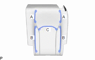
35. INSTALL SEAT COVER WIRE
(a) Install the 6 seat cover wires.
HINT:
- Wire 1000 mm (3.28 ft.) or longer and shaped wires are available as supplied parts.
- For wires 1000 mm (3.28 ft.) or less in length, cut or shape a 1000 mm (3.28 ft.) wire into the dimensions shown in the illustration.
-
Make sure to read Precaution before preparing the wire.
Click here
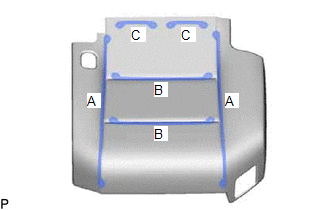
Length:
| A | 420 mm (1.3776 ft.) |
| B | 240 mm (9.45 in.) |
| C | 90 mm (3.54 in.) |
HINT:
The dimension shown in the illustration is the length.
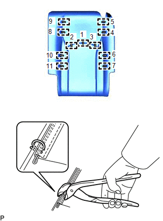
36. INSTALL SEPARATE TYPE REAR SEAT CUSHION COVER
HINT:
When installing a separate type rear seat cushion cover, refer to Precaution in order to prevent wrinkles from forming.
Click here
| (a) Using hog ring pliers, install 20 new hog rings in the order shown in the illustration. NOTICE:
|
|
| (b) Using hog ring pliers, install the separate type rear seat cushion cover to the rear seat cushion pad LH with 6 new hog rings in the order shown in the illustration. NOTICE:
|
|
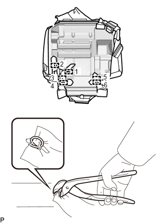
(c) Engage the fastener.
| | Fastener |
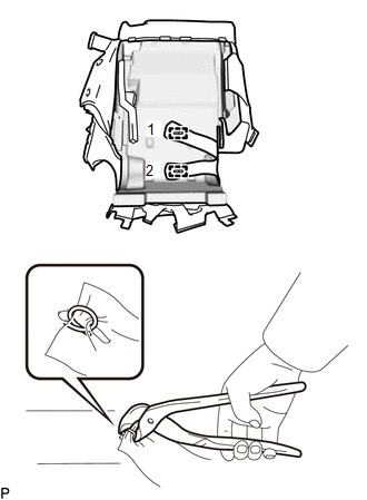
37. INSTALL SEPARATE TYPE REAR SEAT CUSHION COVER WITH PAD
(a) Temporarily install the separate type rear seat cushion cover with pad to the No. 1 seat cushion frame sub-assembly LH.
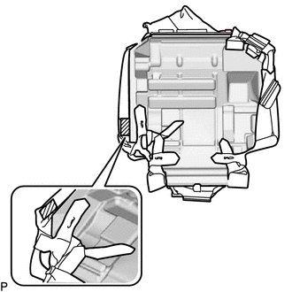
(b) Engage the 9 hooks.
.png)
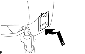
| (c) Engage the hook. |
|
.png)
| (d) Engage the 2 clamps. |
|
.png)
(e) w/ Seat Heater System:
| (1) Engage the 3 clamps. |
|
.png)
(2) Connect the 2 connectors.
| (f) Engage the 4 hooks to install the separate type rear seat cushion cover with pad. |
|
.png)
38. INSTALL REAR SEAT LOCK CONTROL LEVER SUB-ASSEMBLY LH
| (a) Connect the rear seat reclining control cable. |
|
.png)
(b) Engage the guide as shown in the illustration.
| | Install in this Direction |
| (c) Install the rear seat lock control lever sub-assembly LH with the 2 screws. |
|
.png)
| (d) Engage the hook. |
|
.png)
| (e) Engage the clamp to connect the rear seat reclining control cable. |
|
.png)
| (f) Engage the 3 hooks. |
|
.png)
39. INSTALL NO. 1 RECLINING ADJUSTER RELEASE HANDLE LH
| (a) Install the No. 1 reclining adjuster release handle LH with the 3 screws. |
|
.png)
40. INSTALL REAR SEAT COVER CAP LH
| (a) Engage the 2 guides and 2 claws to install the rear seat cover cap LH. |
|
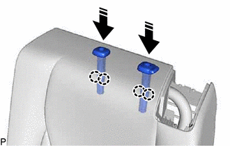
41. INSTALL SEAT ADJUSTER COVER CAP
| (a) Install the 2 seat adjuster cover caps. |
|
.png)
 Installation
INSTALLATION CAUTION / NOTICE / HINT CAUTION: Wear protective gloves. Sharp areas on the seat frame may injure your hands. PROCEDURE 1. INSTALL REAR NO. 1 SEAT ASSEMBLY LH (a) Place the rear No. 1 sea ...

Other materials:
Lexus RX (RX 350L, RX450h) 2016-2026 Repair Manual > Pre-collision System: Invalid Data Received from Brake System Control Module Invalid Serial Data Received (U041881)
DESCRIPTION The skid control ECU (brake actuator assembly) sends signals indicating the status of the vehicle stability control system to the forward recognition camera via CAN communication. If the forward recognition camera receives a vehicle stability control system malfunction signal from the sk ...
Lexus RX (RX 350L, RX450h) 2016-2026 Repair Manual > Transfer System: Problem Symptoms Table
PROBLEM SYMPTOMS TABLE HINT: Use the table below to help determine the cause of problem symptoms. If multiple suspected areas are listed, the potential causes of the symptoms are listed in order of probability in the "Suspected Area" column of the table. Check each symptom by checking the suspected ...
Lexus RX (RX 350L, RX450h) 2016-{YEAR} Owners Manual
- For your information
- Pictorial index
- For safety and security
- Instrument cluster
- Operation of each component
- Driving
- Lexus Display Audio system
- Interior features
- Maintenance and care
- When trouble arises
- Vehicle specifications
- For owners
Lexus RX (RX 350L, RX450h) 2016-{YEAR} Repair Manual

0.0103