Lexus RX (RX 350L, RX450h) 2016-2026 Repair Manual: ACIS Control Circuit
DESCRIPTION
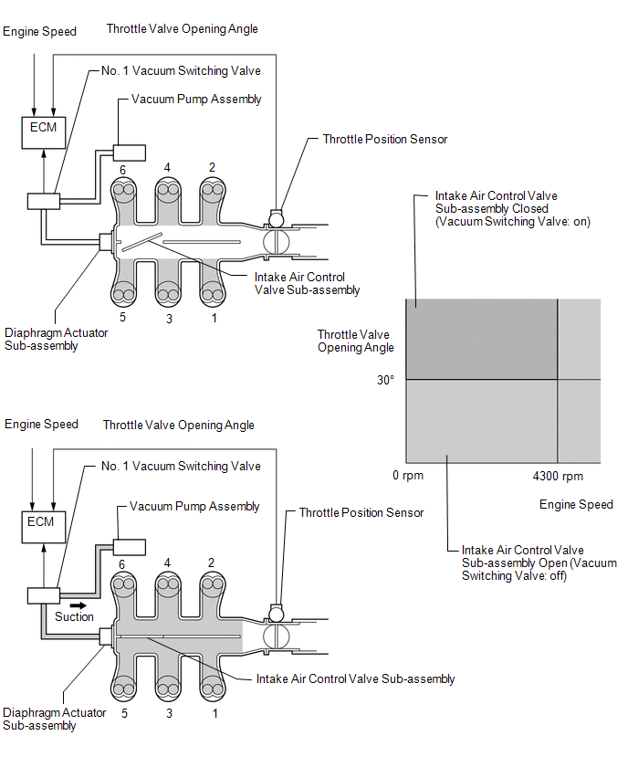
ACIS (Acoustic Control Induction System) controls the opening and closing the intake air control valve sub-assembly built into the intake air surge tank assembly to increase the intake efficiency according to the engine load.
When the engine speed is between 0 and 4300 rpm and the throttle valve opening angle is 30° or more, the ECM activates the No. 1 vacuum switching valve (for intake air control valve sub-assembly) which then applies vacuum from the vacuum pump assembly to the diaphragm actuator sub-assembly and closes the intake air control valve sub-assembly.
When the engine speed and/or throttle valve opening angle are not as specified above, the ECM deactivates the No. 1 vacuum switching valve (for intake air control valve sub-assembly), causing the intake air control valve sub-assembly to open.
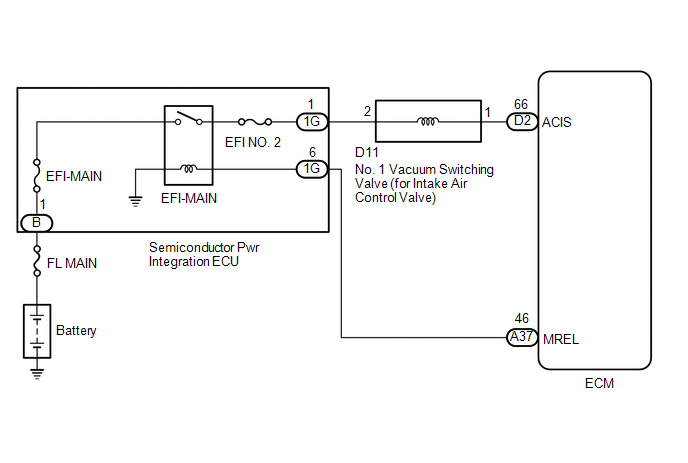
WIRING DIAGRAM
CAUTION / NOTICE / HINT
NOTICE:
Inspect the fuses for circuits related to this system before performing the following procedure.
PROCEDURE
| 1. | PERFORM ACTIVE TEST USING TECHSTREAM (ACTIVATE THE VSV FOR INTAKE CONTROL) |
(a) Connect the Techstream to the DLC3.
(b) Start the engine.
(c) Turn the Techstream on.
(d) Enter the following menus: Powertrain / Engine / Active Test / Activate the VSV for Intake Control.
Powertrain > Engine > Active Test| Tester Display |
|---|
| Activate the VSV for Intake Control |
(e) According to the display on the Techstream, perform the Active Test to operate the No. 1 vacuum switching valve (for intake air control valve sub-assembly) and check for the operating sound of the intake air control valve sub-assembly in the intake air surge tank assembly.
OK:
Operating sounds can be heard.
| OK | .gif) | PROCEED TO NEXT SUSPECTED AREA SHOWN IN PROBLEM SYMPTOMS TABLE |
|
.gif)
| 2. | INSPECT INTAKE AIR SURGE TANK ASSEMBLY (INTAKE AIR CONTROL VALVE SUB-ASSEMBLY OPERATION) |
(a) Inspect the intake air surge tank assembly (intake air control valve sub-assembly).
Click here .gif)
| NG | | REPLACE INTAKE AIR SURGE TANK ASSEMBLY |
|
| 3. | INSPECT VACUUM HOSE SUB-ASSEMBLY (NO. 1 VACUUM SWITCHING VALVE (FOR INTAKE AIR CONTROL VALVE SUB-ASSEMBLY) - INTAKE AIR SURGE TANK ASSEMBLY) |
(a) Check the vacuum hose sub-assembly (No. 1 vacuum switching valve (for intake air control valve sub-assembly) - intake air surge tank assembly) for looseness, disconnection and blockage.
OK:
No looseness, disconnection or blockage.
| NG | | REPAIR OR REPLACE VACUUM HOSE SUB-ASSEMBLY |
|
| 4. | CHECK VACUUM |
| (a) Disconnect the vacuum hose sub-assembly from the No. 1 vacuum switching valve (for intake air control valve sub-assembly). |
|
(b) Start the engine.
(c) Using your finger, confirm that the hose has suction.
| Result | Proceed to |
|---|---|
| Suction applied | A |
| No suction | B |
| B | | GO TO STEP 9 |
|
| 5. | INSPECT NO. 1 VACUUM SWITCHING VALVE (FOR INTAKE AIR CONTROL VALVE SUB-ASSEMBLY) |
(a) Inspect the No. 1 vacuum switching valve (for intake air control valve sub-assembly).
Click here
| NG | | REPLACE NO. 1 VACUUM SWITCHING VALVE (FOR INTAKE AIR CONTROL VALVE SUB-ASSEMBLY) |
|
| 6. | CHECK TERMINAL VOLTAGE (POWER SOURCE OF NO. 1 VACUUM SWITCHING VALVE (FOR INTAKE AIR CONTROL VALVE SUB-ASSEMBLY)) |
| (a) Disconnect the No. 1 vacuum switching valve (for intake air control valve sub-assembly) connector. |
|
(b) Turn the engine switch on (IG).
(c) Measure the voltage according to the value(s) in the table below.
Standard Voltage:
| Tester Connection | Condition | Specified Condition |
|---|---|---|
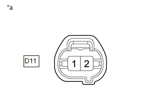
| D11-2 - Body ground | Engine switch on (IG) | 11 to 14 V |
| NG | | GO TO STEP 8 |
|
| 7. | CHECK HARNESS AND CONNECTOR (NO. 1 VACUUM SWITCHING VALVE (FOR INTAKE AIR CONTROL VALVE SUB-ASSEMBLY) - ECM) |
(a) Disconnect the No. 1 vacuum switching valve (for intake air control valve sub-assembly) connector.
(b) Disconnect the ECM connector.
(c) Measure the resistance according to the value(s) in the table below.
Standard Resistance:
| Tester Connection | Condition | Specified Condition |
|---|---|---|
| D11-1 - D2-66 (ACIS) | Always | Below 1 Ω |
| D11-1 or D2-66 (ACIS) - Body ground and other terminals | Always | 10 kΩ or higher |
| OK | | REPLACE ECM |
| NG | | REPAIR OR REPLACE HARNESS OR CONNECTOR |
| 8. | CHECK HARNESS AND CONNECTOR (SEMICONDUCTOR PWR INTEGRATION ECU - NO. 1 VACUUM SWITCHING VALVE (FOR INTAKE AIR CONTROL VALVE SUB-ASSEMBLY)) |
(a) Disconnect the semiconductor pwr integration ECU connector.
(b) Disconnect the No. 1 vacuum switching valve (for intake air control valve sub-assembly) connector.
(c) Measure the resistance according to the value(s) in the table below.
Standard Resistance:
| Tester Connection | Condition | Specified Condition |
|---|---|---|
| 1G-1 - D11-2 | Always | Below 1 Ω |
| 1G-1 or D11-2 - Body ground and other terminals | Always | 10 kΩ or higher |
| OK | | GO TO ECM POWER SOURCE CIRCUIT |
| NG | | REPAIR OR REPLACE HARNESS OR CONNECTOR |
| 9. | INSPECT VACUUM PUMP ASSEMBLY |
(a) Inspect the vacuum pump assembly.
Click here
| OK | | REPAIR OR REPLACE VACUUM HOSE SUB-ASSEMBLY (NO. 1 VACUUM SWITCHING VALVE (FOR INTAKE AIR CONTROL VALVE SUB-ASSEMBLY) - VACUUM PUMP ASSEMBLY) |
| NG | | REPLACE VACUUM PUMP ASSEMBLY |
 VC Output Circuit
DESCRIPTION The ECM constantly generates a 5 V power source voltage from the battery voltage supplied to the +B, +B2 (BATT) terminals to operate the microprocessor. The ECM also provides this power to ...
 Brake Override System
DESCRIPTION When the vehicle is being driven, depressing the accelerator pedal sensor assembly and brake pedal will activate the brake override system to restrict engine output. The conditions for act ...
Other materials:
Lexus RX (RX 350L, RX450h) 2016-2026 Repair Manual > Front Power Seat Control System (w/ Memory): Customize Parameters
CUSTOMIZE PARAMETERS CUSTOMIZE FRONT POWER SEAT CONTROL SYSTEM (w/ Memory) HINT: The following items can be customized. NOTICE:
When the customer requests a change in a function, first make sure that the function can be customized.
Record the current settings before customizing.
(a) Customiz ...
Lexus RX (RX 350L, RX450h) 2016-2026 Repair Manual > Sfi System: Crankshaft Position - Camshaft Position Correlation Bank 1 Sensor A (P001600,P001800)
DESCRIPTION In the VVT (Variable Valve Timing) system, the appropriate intake valve open and close timing is controlled by the ECM. The ECM performs intake valve control by performing the following: 1) controlling the intake camshaft, cam timing oil control solenoid assembly, camshaft timing gear bo ...
Lexus RX (RX 350L, RX450h) 2016-{YEAR} Owners Manual
- For your information
- Pictorial index
- For safety and security
- Instrument cluster
- Operation of each component
- Driving
- Lexus Display Audio system
- Interior features
- Maintenance and care
- When trouble arises
- Vehicle specifications
- For owners
Lexus RX (RX 350L, RX450h) 2016-{YEAR} Repair Manual

0.0104