Lexus RX (RX 350L, RX450h) 2016-2026 Repair Manual: VC Output Circuit
DESCRIPTION
The ECM constantly generates a 5 V power source voltage from the battery voltage supplied to the +B, +B2 (BATT) terminals to operate the microprocessor. The ECM also provides this power to the sensors through the VC output circuit.
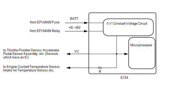
When the VC circuit has a short circuit, the microprocessor in the ECM and sensors that are supplied power through the VC circuit are deactivated because power is not supplied from the VC circuit. When the system is in this condition, it will not start.
WIRING DIAGRAM
-
For the circuit diagram of the ECM power source refer to the ECM power source circuit.
Click here
.gif)
-
VC Output Circuit
CAUTION / NOTICE / HINT
NOTICE:
Check the fuses for circuits related to this system before performing the following inspection procedure.
PROCEDURE
| 1. | CHECK CONNECTION BETWEEN TECHSTREAM AND ECM |
(a) Connect the Techstream to the DLC3.
(b) Turn the engine switch on (IG).
(c) Turn the Techstream on.
(d) Check the communication between the Techstream and ECM.
HINT:
It can be checked using the "Engine" item of the Data List.
| Result | Proceed to |
|---|---|
| Communication is not possible | A |
| Communication is possible | B |
| B | .gif) | PROCEED TO NEXT SUSPECTED AREA SHOWN IN PROBLEM SYMPTOMS TABLE |
|
.gif)
| 2. | CHECK EFI NO. 2 FUSE VOLTAGE |
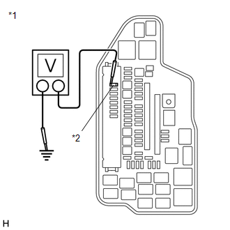
| *1 | Engine Room Relay Block and Junction Block Assembly |
| *2 | EFI NO. 2 Fuse |
(a) Turn the engine switch on (IG).
(b) Measure the voltage according to the value(s) in the table below.
Standard Voltage:
| Tester Connection | Condition | Specified Condition |
|---|---|---|
| 1 (EFI NO. 2 fuse) - Body ground | Engine switch on (IG) | 11 to 14 V |
HINT:
- Check the fuse with it installed to the engine room relay block and junction block assembly.
- If the result is not as specified, since current is not flowing to the +B and +B2 terminals of the ECM, the system may not be started.
| NG | | GO TO ECM POWER SOURCE CIRCUIT |
|
| 3. | CHECK CONNECTION BETWEEN TECHSTREAM AND ECM (THROTTLE POSITION SENSOR) |
(a) Disconnect the throttle body with motor assembly connector.
(b) Turn the engine switch on (IG).
(c) Turn the Techstream on.
(d) Check the communication between the Techstream and ECM.
HINT:
It can be checked using the "Engine" item of the Data List.
| Result | Proceed to |
|---|---|
| Communication is not possible | A |
| Communication is possible | B |
HINT:
Perform "Inspection After Repair" after replacing the throttle body with motor assembly.
Click here
| B | | REPLACE THROTTLE BODY WITH MOTOR ASSEMBLY |
|
| 4. | CHECK CONNECTION BETWEEN TECHSTREAM AND ECM (ACCELERATOR PEDAL POSITION SENSOR) |
(a) Disconnect the accelerator pedal sensor assembly connector.
(b) Turn the engine switch on (IG).
(c) Turn the Techstream on.
(d) Check the communication between the Techstream and ECM.
HINT:
It can be checked using the "Engine" item of the Data List.
| Result | Proceed to |
|---|---|
| Communication is not possible | A |
| Communication is possible | B |
| B | | REPLACE ACCELERATOR PEDAL SENSOR ASSEMBLY |
|
| 5. | CHECK CONNECTION BETWEEN TECHSTREAM AND ECM (CRANKSHAFT POSITION SENSOR) |
(a) Disconnect the crankshaft position sensor connector.
(b) Turn the engine switch on (IG).
(c) Turn the Techstream on.
(d) Check the communication between the Techstream and ECM.
HINT:
It can be checked using the "Engine" item of the Data List.
| Result | Proceed to |
|---|---|
| Communication is not possible | A |
| Communication is possible | B |
| B | | REPLACE CRANKSHAFT POSITION SENSOR |
|
| 6. | CHECK CONNECTION BETWEEN TECHSTREAM AND ECM (VVT SENSOR (FOR INTAKE CAMSHAFT OF BANK 1)) |
(a) Disconnect the VVT sensor (for intake camshaft of bank 1) connector.
(b) Turn the engine switch on (IG).
(c) Turn the Techstream on.
(d) Check the communication between the Techstream and ECM.
HINT:
It can be checked using the "Engine" item of the Data List.
| Result | Proceed to |
|---|---|
| Communication is not possible | A |
| Communication is possible | B |
| B | | REPLACE VVT SENSOR (FOR INTAKE CAMSHAFT OF BANK 1) |
|
| 7. | CHECK CONNECTION BETWEEN TECHSTREAM AND ECM (VVT SENSOR (FOR INTAKE CAMSHAFT OF BANK 2)) |
(a) Disconnect the VVT sensor (for intake camshaft of bank 2) connector.
(b) Turn the engine switch on (IG).
(c) Turn the Techstream on.
(d) Check the communication between the Techstream and ECM.
HINT:
It can be checked using the "Engine" item of the Data List.
| Result | Proceed to |
|---|---|
| Communication is not possible | A |
| Communication is possible | B |
| B | | REPLACE VVT SENSOR (FOR INTAKE CAMSHAFT OF BANK 2) |
|
| 8. | CHECK CONNECTION BETWEEN TECHSTREAM AND ECM (VVT SENSOR (FOR EXHAUST CAMSHAFT OF BANK 1)) |
(a) Disconnect the VVT sensor (for exhaust camshaft of bank 1) connector.
(b) Turn the engine switch on (IG).
(c) Turn the Techstream on.
(d) Check the communication between the Techstream and ECM.
HINT:
It can be checked using the "Engine" item of the Data List.
| Result | Proceed to |
|---|---|
| Communication is not possible | A |
| Communication is possible | B |
| B | | REPLACE VVT SENSOR (FOR EXHAUST CAMSHAFT OF BANK 1) |
|
| 9. | CHECK CONNECTION BETWEEN TECHSTREAM AND ECM (VVT SENSOR (FOR EXHAUST CAMSHAFT OF BANK 2)) |
(a) Disconnect the VVT sensor (for exhaust camshaft of bank 2) connector.
(b) Turn the engine switch on (IG).
(c) Turn the Techstream on.
(d) Check the communication between the Techstream and ECM.
HINT:
It can be checked using the "Engine" item of the Data List.
| Result | Proceed to |
|---|---|
| Communication is not possible | A |
| Communication is possible | B |
| B | | REPLACE VVT SENSOR (FOR EXHAUST CAMSHAFT OF BANK 2) |
|
| 10. | CHECK CONNECTION BETWEEN TECHSTREAM AND ECM (FUEL PRESSURE SENSOR (FOR HIGH PRESSURE SIDE)) |
(a) Disconnect the fuel pressure sensor (for high pressure side) connector.
(b) Turn the engine switch on (IG).
(c) Turn the Techstream on.
(d) Check the communication between the Techstream and ECM.
HINT:
It can be checked using the "Engine" item of the Data List.
| Result | Proceed to |
|---|---|
| Communication is not possible | A |
| Communication is possible | B |
HINT:
Perform "Inspection After Repair" after replacing the fuel pressure sensor (for high pressure side).
Click here
| B | | REPLACE FUEL DELIVERY PIPE WITH SENSOR ASSEMBLY LH (FUEL PRESSURE SENSOR (FOR HIGH PRESSURE SIDE)) |
|
| 11. | CHECK CONNECTION BETWEEN TECHSTREAM AND ECM (FUEL PRESSURE SENSOR (FOR LOW PRESSURE SIDE)) |
(a) Disconnect the fuel pressure sensor (for low pressure side) connector.
(b) Turn the engine switch on (IG).
(c) Turn the Techstream on.
(d) Check the communication between the Techstream and ECM.
HINT:
It can be checked using the "Engine" item of the Data List.
| Result | Proceed to |
|---|---|
| Communication is not possible | A |
| Communication is possible | B |
HINT:
Perform "Inspection After Repair" after replacing the fuel pressure sensor (for low pressure side).
Click here
| B | | REPLACE FUEL DELIVERY PIPE SUB-ASSEMBLY (FUEL PRESSURE SENSOR (FOR LOW PRESSURE SIDE)) |
|
| 12. | CHECK CONNECTION BETWEEN TECHSTREAM AND ECM (MASS AIR FLOW METER SUB-ASSEMBLY) |
(a) Disconnect the mass air flow meter sub-assembly connector.
(b) Turn the engine switch on (IG).
(c) Turn the Techstream on.
(d) Check the communication between the Techstream and ECM.
HINT:
It can be checked using the "Engine" item of the Data List.
| Result | Proceed to |
|---|---|
| Communication is not possible | A |
| Communication is possible | B |
| B | | REPLACE MASS AIR FLOW METER SUB-ASSEMBLY |
|
| 13. | CHECK CONNECTION BETWEEN TECHSTREAM AND ECM (CANISTER PUMP MODULE) |
(a) Disconnect the canister pump module connector.
(b) Turn the engine switch on (IG).
(c) Turn the Techstream on.
(d) Check the communication between the Techstream and ECM.
HINT:
It can be checked using the "Engine" item of the Data List.
| Result | Proceed to |
|---|---|
| Communication is not possible | A |
| Communication is possible | B |
| B | | REPLACE CANISTER PUMP MODULE |
|
| 14. | CHECK HARNESS AND CONNECTOR |
(a) Disconnect the throttle body with motor assembly connector.
(b) Disconnect the accelerator pedal sensor assembly connector.
(c) Disconnect the crankshaft position sensor connector.
(d) Disconnect the VVT sensor (for intake camshaft of bank 1) connector.
(e) Disconnect the VVT sensor (for intake camshaft of bank 2) connector.
(f) Disconnect the VVT sensor (for exhaust camshaft of bank 1) connector.
(g) Disconnect the VVT sensor (for exhaust camshaft of bank 2) connector.
(h) Disconnect the fuel pressure sensor (for high pressure side) connector.
(i) Disconnect the fuel pressure sensor (for low pressure side) connector.
(j) Disconnect the mass air flow meter sub-assembly connector.
(k) Disconnect the ECM connectors.
(l) Disconnect the canister pump module connector.
(m) Measure the resistance according to the value(s) in the table below.
Standard Resistance:
| Tester Connection | Condition | Specified Condition |
|---|---|---|
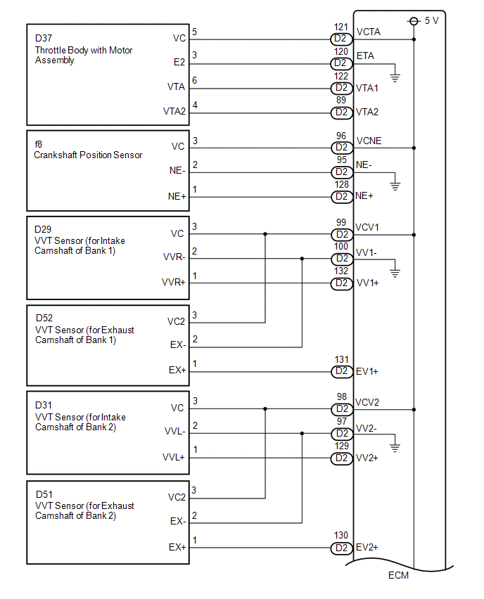
| D2-121 (VCTA) - Body ground | Always | 10 kΩ or higher |
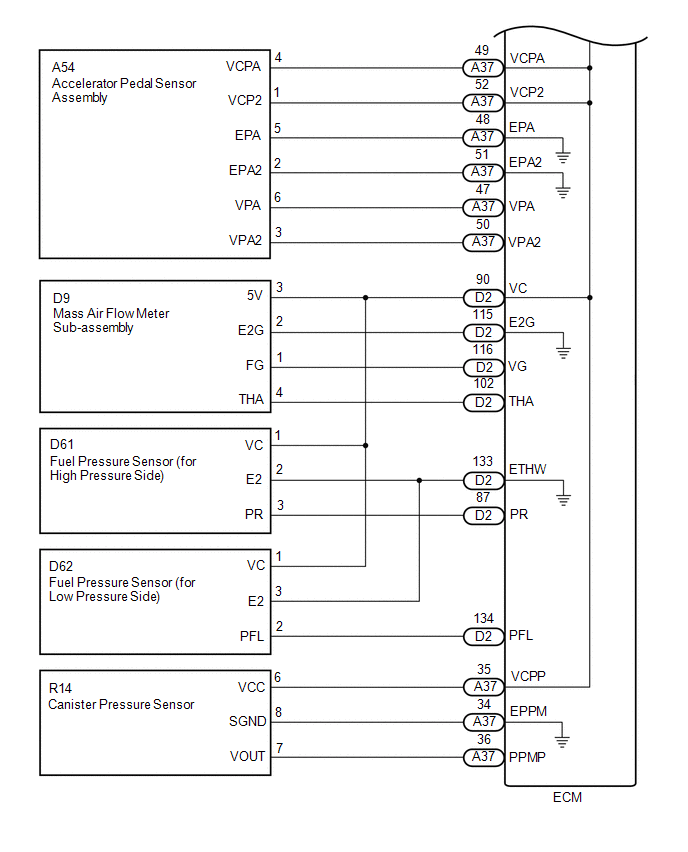
| A37-49 (VCPA) - Body ground | Always | 10 kΩ or higher |
| A37-52 (VCP2) - Body ground | Always | 10 kΩ or higher |
| D2-96 (VCNE) - Body ground | Always | 10 kΩ or higher |
| D2-99 (VCV1) - Body ground | Always | 10 kΩ or higher |
| D2-98 (VCV2) - Body ground | Always | 10 kΩ or higher |
| D2-90 (VC) - Body ground | Always | 10 kΩ or higher |
| A37-35 (VCPP) - Body ground | Always | 10 kΩ or higher |
| A37-2 (+B) - 1 (EFI NO. 2 fuse) | Always | Below 1 Ω |
| A37-3 (+B2) - 1 (EFI NO. 2 fuse) | Always | Below 1 Ω |
| A37-2 (+B) - Body ground | Always | 10 kΩ or higher |
| A37-3 (+B2) - Body ground | Always | 10 kΩ or higher |
| OK | | REPLACE ECM |
| NG | | REPAIR OR REPLACE HARNESS OR CONNECTOR |
 Starter Signal Circuit
DESCRIPTION While the engine is being cranked, current flows from terminal STAR of the certification ECU (smart key ECU assembly) to the park/neutral position switch assembly and to terminal STA of th ...
 ACIS Control Circuit
DESCRIPTION ACIS (Acoustic Control Induction System) controls the opening and closing the intake air control valve sub-assembly built into the intake air surge tank assembly to increase the intake eff ...
Other materials:
Lexus RX (RX 350L, RX450h) 2016-2026 Repair Manual > Dynamic Radar Cruise Control System: Cruise Control Switch Circuit
DESCRIPTION The cruise control main switch is used to turn the dynamic radar cruise control system on and off, as well as operate 7 functions: SET, - (COAST), TAP-DOWN, RES (RESUME), + (ACCEL), TAP-UP and CANCEL. The SET, TAP-DOWN and - (COAST) functions, and the RES (RESUME), TAP-UP and + (ACCEL) f ...
Lexus RX (RX 350L, RX450h) 2016-2026 Repair Manual > Power Back Door Warning Buzzer: Removal
REMOVAL PROCEDURE 1. REMOVE BACK WINDOW UPPER PANEL TRIM (w/o Rear No. 2 Seat) Click here 2. REMOVE BACK WINDOW UPPER PANEL TRIM (w/ Rear No. 2 Seat) Click here 3. REMOVE BACK DOOR TRIM COVER LH (w/o Rear No. 2 Seat) Click here 4. REMOVE BACK DOOR TRIM COVER LH (w/ Rear No. 2 Seat) Click he ...
Lexus RX (RX 350L, RX450h) 2016-{YEAR} Owners Manual
- For your information
- Pictorial index
- For safety and security
- Instrument cluster
- Operation of each component
- Driving
- Lexus Display Audio system
- Interior features
- Maintenance and care
- When trouble arises
- Vehicle specifications
- For owners
Lexus RX (RX 350L, RX450h) 2016-{YEAR} Repair Manual

0.0117