Lexus RX (RX 350L, RX450h) 2016-2026 Repair Manual: Installation
INSTALLATION
PROCEDURE
1. INSTALL STUD BOLT
NOTICE:
If a stud bolt is deformed or its threads are damaged, replace it.
| (a) Using an 8 mm socket wrench, install the stud bolt to the front No. 1 engine mounting bracket LH. Torque: 10 N·m {102 kgf·cm, 7 ft·lbf} |
|
.png)
2. INSTALL RADIATOR PIPE CLAMP
(a) Install the radiator pipe clamp to the camshaft housing sub-assembly LH with the bolt.
Torque:
5.5 N·m {56 kgf·cm, 49 in·lbf}
3. INSTALL WIRE HARNESS CLAMP BRACKET
(a) Install the wire harness clamp bracket to the camshaft housing sub-assembly with the bolt.
Torque:
13 N·m {133 kgf·cm, 10 ft·lbf}
4. INSTALL NO. 1 EXHAUST PIPE SUPPORT BRACKET
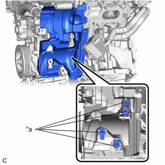
(a) Install the No. 1 exhaust pipe support bracket to the oil pan sub-assembly with the 2 bolts.
Torque:
21 N·m {214 kgf·cm, 15 ft·lbf}
5. INSTALL DRIVE SHAFT BEARING BRACKET (for 2WD)
(a) Install the drive shaft bearing bracket to the cylinder block sub-assembly with the 3 bolts.
Torque:
63.7 N·m {650 kgf·cm, 47 ft·lbf}
NOTICE:
Make sure that there is no oil on the threads of the bolts.
6. INSTALL NO. 2 TRANSFER STIFFENER PLATE (for AWD)
(a) Install the No. 2 transfer stiffener plate to the cylinder block sub-assembly with the 3 bolts.
Torque:
64 N·m {653 kgf·cm, 47 ft·lbf}
7. INSTALL NO. 5 CYLINDER BLOCK INSULATOR (w/ Oil Cooler)
| (a) Install the No. 5 cylinder block insulator to the engine assembly. NOTICE: Make sure that the No. 5 cylinder block insulator is not covering any fastener surface. |
|
8. INSTALL ENGINE OIL LEVEL DIPSTICK GUIDE
(a) Install a new engine oil level dipstick guide O-ring to the engine oil level dipstick guide.
(b) Apply a light coat of engine oil to the engine oil level dipstick guide O-ring.
(c) Insert the engine oil level dipstick guide end into the oil pan sub-assembly.
(d) Install the engine oil level dipstick guide to the camshaft housing sub-assembly LH with the bolt.
Torque:
21 N·m {214 kgf·cm, 15 ft·lbf}
(e) Install the engine oil level dipstick to the engine oil level dipstick guide.
9. INSTALL WATER PUMP PULLEY
Click here .gif)
10. INSTALL V-RIBBED BELT TENSIONER ASSEMBLY
(a) Install the V-ribbed belt tensioner assembly with the 2 bolts.
Torque:
43 N·m {438 kgf·cm, 32 ft·lbf}
11. INSTALL NO. 2 IDLER PULLEY SUB-ASSEMBLY
Click here
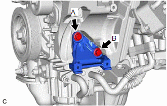
12. INSTALL NO. 1 COMPRESSOR MOUNTING BRACKET
| (a) Install the No. 1 compressor mounting bracket to the cylinder block sub-assembly with the 2 bolts. Torque: 43 N·m {438 kgf·cm, 32 ft·lbf} NOTICE: Temporarily tighten the bolt (A), and then fully tighten the 2 bolts in the order of (B) and (A). |
|
13. INSTALL COMPRESSOR AND MAGNETIC CLUTCH
Click here
14. INSTALL GENERATOR ASSEMBLY
-
for 180A Type:
Click here
-
for 150A Type:
Click here
15. INSTALL V-RIBBED BELT
Click here
16. INSTALL NO. 2 VENTILATION HOSE
(a) Install the No. 2 ventilation hose to the cylinder head cover sub-assembly and slide the clip to secure it.
17. INSTALL VENTILATION HOSE
(a) Install the ventilation hose to the PCV valve (ventilation valve sub-assembly) and slide the clip to secure it.
18. INSTALL NO. 2 WATER BY-PASS HOSE
(a) Install the No. 2 water by-pass hose to the water outlet and slide the clip to secure it.
19. INSTALL NO. 3 WATER BY-PASS HOSE
(a) Install the No. 3 water by-pass hose to the water inlet pipe and slide the clip to secure it.
20. INSTALL VACUUM PUMP ASSEMBLY
Click here
21. INSTALL IGNITION COIL ASSEMBLY
Click here
22. INSTALL SENSOR WIRE
(a) Engage the 2 clamps and install the sensor wire to the water inlet pipe with the bolt.
Torque:
10 N·m {102 kgf·cm, 7 ft·lbf}
23. INSTALL KNOCK CONTROL SENSOR
Click here
 Disassembly
DISASSEMBLY PROCEDURE 1. REMOVE OIL FILLER CAP SUB-ASSEMBLY (a) Remove the oil filler cap sub-assembly from the cylinder head cover sub-assembly LH. (b) Remove the oil filler cap gas ...
 Reassembly
REASSEMBLY PROCEDURE 1. INSTALL WATER INLET PIPE (a) Install the water inlet pipe with the 2 bolts. Torque: 10 N·m {102 kgf·cm, 7 ft·lbf} *A w/o Oil Cooler *B w/ Oil Cooler ...
Other materials:
Lexus RX (RX 350L, RX450h) 2016-2026 Repair Manual > Front Camera System: Software Incompatibility with Body Control Module Invalid/Incompatible Software Component (U032257)
DESCRIPTION The forward recognition camera receives vehicle information from the main body ECU (multiplex network body ECU) via CAN communication. DTC U032257 is stored when the vehicle information from the main body ECU (multiplex network body ECU) and that stored in the forward recognition camera ...
Lexus RX (RX 350L, RX450h) 2016-2026 Repair Manual > Stop Light Switch: On-vehicle Inspection
ON-VEHICLE INSPECTION PROCEDURE 1. INSPECT STOP LIGHT SWITCH ASSEMBLY (a) Disconnect the A55 stop light switch assembly connector. *a Front view of wire harness connector (to Stop Light Switch Assembly) (b) Measure the voltage and resistance on the wire harness side connec ...
Lexus RX (RX 350L, RX450h) 2016-{YEAR} Owners Manual
- For your information
- Pictorial index
- For safety and security
- Instrument cluster
- Operation of each component
- Driving
- Lexus Display Audio system
- Interior features
- Maintenance and care
- When trouble arises
- Vehicle specifications
- For owners
Lexus RX (RX 350L, RX450h) 2016-{YEAR} Repair Manual

0.0121