Lexus RX (RX 350L, RX450h) 2016-2026 Repair Manual: Removal
REMOVAL
CAUTION / NOTICE / HINT
The necessary procedures (adjustment, calibration, initialization, or registration) that must be performed after parts are removed and installed, or replaced during engine unit removal/installation are shown below.
Necessary Procedure After Parts Removed/Installed/Replaced| Replaced Part or Performed Procedure | Necessary Procedure | Effect/Inoperative Function when Necessary Procedure not Performed | Link |
|---|---|---|---|
|
*1: When performing learning using the Techstream.
Click here | |||
| Disconnect cable from negative battery terminal | Memorize steering angle neutral point | Lane Control System | |
| Pre-collision system | |||
| Intelligent clearance sonar system*1 | |||
| Lighting system (w/ Automatic Headlight Beam Level Control System) | | ||
| Parking assist monitor system | | ||
| Panoramic view monitor system | | ||
| Initialize back door lock | Power door lock control system | | |
| Reset back door close position | Power Back Door System (w/ Outside Door Control Switch) | | |
| Replacement of ECM | Vehicle Identification Number (VIN) registration | MIL comes on | |
| ECU Communication ID Registration (Immobiliser system) | Engine start function | | |
| Perform code registration (Immobiliser system) |
| | |
| Inspection After Repair |
| |
| Replacement of automatic transaxle assembly | Perform the following procedures in the order shown:
|
| for U881E Registration: for U881E Initialization: for U881F Registration: for U881F Initialization: |
| Replacement of ECM (If possible, read the transaxle compensation code from the previous ECM) | Perform the following procedures in the order shown:
| ||
| Replacement of ECM (If impossible, read the transaxle compensation code from the previous ECM) | Perform the following procedures in the order shown:
| ||
| Front wheel alignment adjustment | Calibration |
| |
| Suspension, tires, etc. (The vehicle height changes because of suspension or tire replacement) |
|
| |
| Rear television camera assembly optical axis (Back camera position setting) | Parking assist monitor system | for Initialization: for Calibration: | |
| Panoramic view monitor system | for Initialization: for Calibration: | |
| Initialize No. 1 headlight ECU sub-assembly LH | Lighting System (w/ Automatic Headlight Beam Level Control System) | | |
PROCEDURE
1. REMOVE AUTOMATIC TRANSAXLE ASSEMBLY
for U881E: Click here .gif)
for U881F: Click here
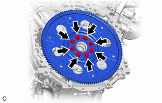
2. REMOVE DRIVE PLATE AND RING GEAR SUB-ASSEMBLY
| (a) Using SST, hold the crankshaft pulley. SST: 09213-70011 09213-70020 SST: 09330-00021 |
|
.png)
| (b) Remove the 8 bolts, the rear drive plate spacer, the drive plate and ring gear sub-assembly and the No. 1 crankshaft position sensor plate. |
|
3. REMOVE REAR ENGINE OIL SEAL
| (a) Using a knife, cut through the lip of the rear engine oil seal. |
|
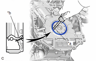
(b) Using a screwdriver with its tip wrapped with protective tape, pry out the rear engine oil seal.
NOTICE:
Be careful not to damage the crankshaft.
 Installation
INSTALLATION PROCEDURE 1. INSTALL REAR ENGINE OIL SEAL (a) Apply MP grease to the lip of a new rear engine oil seal. *1 Rear Engine Oil Seal Retainer *a Oil Seal Protrusion Hei ...
 2gr-fks (fuel)
...
Other materials:
Lexus RX (RX 350L, RX450h) 2016-2026 Repair Manual > Park / Neutral Position Switch: Installation
INSTALLATION PROCEDURE 1. INSTALL PARK/NEUTRAL POSITION SWITCH ASSEMBLY (a) Move the shift lever to N. (b) Temporarily install the park/neutral position switch assembly to the automatic transaxle case sub-assembly with the 2 bolts. NOTICE: Before installing the park/neutral position switch assembly, ...
Lexus RX (RX 350L, RX450h) 2016-2026 Repair Manual > Rear Seat Assembly (for 60/40 Split Seat Type Rh Side): Inspection
INSPECTION PROCEDURE 1. PRECAUTION NOTICE: After performing the following check, initialize the fold seat control ECU (initial position reset and initial position memorization). Click here 2. INSPECT REAR SEATBACK FRAME SUB-ASSEMBLY RH (a) Check the operation of the reclining motor. (1) Apply batt ...
Lexus RX (RX 350L, RX450h) 2016-{YEAR} Owners Manual
- For your information
- Pictorial index
- For safety and security
- Instrument cluster
- Operation of each component
- Driving
- Lexus Display Audio system
- Interior features
- Maintenance and care
- When trouble arises
- Vehicle specifications
- For owners
Lexus RX (RX 350L, RX450h) 2016-{YEAR} Repair Manual

0.0105