Lexus RX (RX 350L, RX450h) 2016-2026 Repair Manual: Removal
REMOVAL
CAUTION / NOTICE / HINT
The necessary procedures (adjustment, calibration, initialization or registration) that must be performed after parts are removed and installed, or replaced during fuel injector assembly removal/installation are shown below.
Necessary Procedures After Parts Removed/Installed/Replaced| Replaced Part or Performed Procedure | Necessary Procedure | Effect/Inoperative Function when Necessary Procedure not Performed | Link |
|---|---|---|---|
|
*1: When performing learning using the Techstream.
Click here | |||
| Battery terminal is disconnected/reconnected | Memorize steering angle neutral point | Lane Control System | |
| Pre-collision system | |||
| Intelligent clearance sonar system*1 | |||
| Lighting system (w/ Automatic Headlight Beam Level Control System) | | ||
| Parking assist monitor system | | ||
| Panoramic view monitor system | | ||
| Initialize back door lock | Power door lock control system | | |
| Reset back door close position | Power Back Door System (w/ Outside Door Control Switch) | | |
| Inspection After Repair |
| |
PROCEDURE
1. REMOVE FUEL PUMP ASSEMBLY (for High Pressure)
Click here .gif)
2. REMOVE NO. 2 FUEL PIPE SUB-ASSEMBLY
CAUTION:
To prevent serious injury due to fuel spray from the high-pressure fuel lines, always discharge fuel system pressure before removing any fuel system components.
.png)
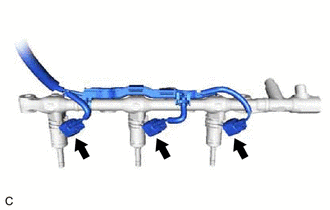
| (a) Using a 17 mm union nut wrench, loosen the 2 union nuts of the No. 2 fuel pipe sub-assembly. |
|
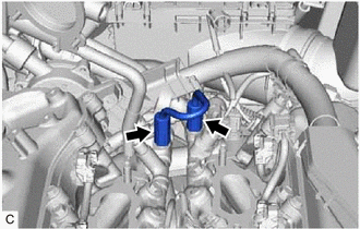
(b) Remove the No. 2 fuel pipe sub-assembly from the fuel delivery pipe with sensor assembly LH and fuel delivery pipe RH.
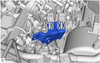
3. REMOVE WIRE HARNESS CLAMP BRACKET
| (a) Disconnect the No. 6 engine wire connector and No. 7 engine wire connector. |
|
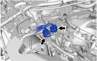
| (b) Disengage the 2 clamps to remove the wire harness clamp bracket. |
|
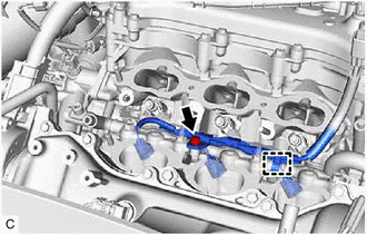
4. REMOVE FUEL DELIVERY PIPE WITH SENSOR ASSEMBLY LH
| (a) Disconnect the fuel pressure sensor connector. |
|

| (b) Remove the bolt. |
|
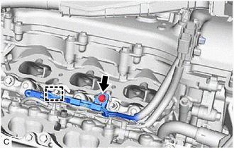
(c) Disengage the clamp to disconnect the No. 7 engine wire from the fuel delivery pipe with sensor assembly LH.
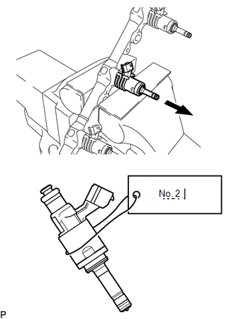
(d) Remove the 2 bolts, 2 nuts and fuel delivery pipe with sensor assembly LH with the fuel injector assemblies.
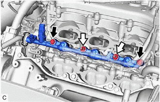
.png) | Bolt |
.png) | Nut |
NOTICE:
- Make sure not to touch or strike the tips of the fuel injector assemblies.
- Pull and remove the fuel delivery pipe with sensor assembly LH in a straight line without tilting it.
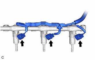
| (e) Disconnect the 3 fuel injector assembly connectors. |
|
5. REMOVE FUEL DELIVERY PIPE RH
| (a) Remove the bolt. |
|
(b) Disengage the clamp to disconnect the No. 6 engine wire from the fuel delivery pipe RH.
(c) Remove the 2 bolts, 2 nuts and fuel delivery pipe RH with the fuel injector assemblies.
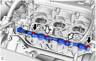
| | Bolt |
| | Nut |
NOTICE:
- Make sure not to touch or strike the tips of the fuel injector assemblies.
- Pull and remove the fuel delivery pipe RH in a straight line without tilting it.
| (d) Disconnect the 3 fuel injector assembly connectors. |
|
6. REMOVE FUEL INJECTOR ASSEMBLY
| (a) Secure the fuel delivery pipe with sensor assembly LH and fuel delivery pipe RH in a vise between aluminum plates and pull out the 6 fuel injector assemblies. NOTICE:
|
|
(b) Remove the nozzle holder clamp from each fuel injector assembly.
(c) Using needle nose pliers, remove the No. 3 fuel injector back-up ring from each fuel injector assembly.
NOTICE:
Do not damage the area that contacts the O-ring.
(d) Remove the O-ring and No. 1 fuel injector back-up ring from each fuel injector assembly.
(e) Remove the C-ring and injector vibration insulator from each fuel injector assembly.
7. REMOVE FUEL INJECTOR SEAL
| (a) Using the tip of needle nose pliers, pinch and pull the fuel injector seal at several points to stretch it. NOTICE:
|
|
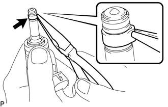
(b) Remove the fuel injector seal from each fuel injector assembly.
 Inspection
INSPECTION PROCEDURE 1. INSPECT FUEL INJECTOR ASSEMBLY NOTICE: This inspection is for checking the fuel injector assembly for an open or short. Because the fuel injector assembly of this vehicle is a ...
 Installation
INSTALLATION PROCEDURE 1. INSTALL FUEL INJECTOR SEAL (a) Apply engine conditioner to the area shown in the illustration. Using a piece of cloth, clean carbon deposits from the fuel injector assembl ...
Other materials:
Lexus RX (RX 350L, RX450h) 2016-2026 Repair Manual > Navigation System: Radio Broadcast cannot be Received or Poor Reception
CAUTION / NOTICE / HINT NOTICE: Depending on the parts that are replaced during vehicle inspection or maintenance, performing initialization, registration or calibration may be needed. Refer to Precaution for Navigation System. Click here PROCEDURE 1. CHECK RADIO RECEIVER ASSEMBLY (a) Che ...
Lexus RX (RX 350L, RX450h) 2016-2026 Repair Manual > Personal Light: Inspection
INSPECTION PROCEDURE 1. INSPECT MAP LIGHT ASSEMBLY (a) Measure the resistance according to the value(s) in the table below. Standard Resistance: Tester Connection Condition Specified Condition U11-4 (+B1) - U12-14 (RIFR) Always Below 1 Ω U12-10 (RLMP) - U12-20 (GND9) Always ...
Lexus RX (RX 350L, RX450h) 2016-{YEAR} Owners Manual
- For your information
- Pictorial index
- For safety and security
- Instrument cluster
- Operation of each component
- Driving
- Lexus Display Audio system
- Interior features
- Maintenance and care
- When trouble arises
- Vehicle specifications
- For owners
Lexus RX (RX 350L, RX450h) 2016-{YEAR} Repair Manual

0.0142