
Lexus RX (RX 350L, RX450h) 2016-2026 Repair Manual: How To Use This Manual
General Information
GENERAL INFORMATION
GENERAL DESCRIPTION
(a) This manual is written in accordance with SAE J2008.
(b) Repair operations can be separated mainly into the following 3 processes:
(1) Diagnosis
(2) Removing/Installing, Replacing, Disassembling/Reassembling, Checking and Adjusting
(3) Final Inspection
(c) The following procedures are omitted from this manual. However, these procedures must be performed.
(1) Use a jack or lift to perform operations.
(2) Clean all removed parts.
(3) Perform a visual check before and after performing any work.
PREPARATION
(a) Use of Special Service Tools (SST) and Special Service Materials (SSM) may be required, depending on the repair procedure. Be sure to use SST and SSM when they are required and follow the work procedure properly. A list of SST and SSM is in the "Preparation" section of this manual.
REPAIR PROCEDURES
(a) A component illustration is placed under the title where necessary.
(b) Non-reusable parts, grease application areas, precoated parts and torque specifications are noted in the component illustrations.
- The following illustration is an example.
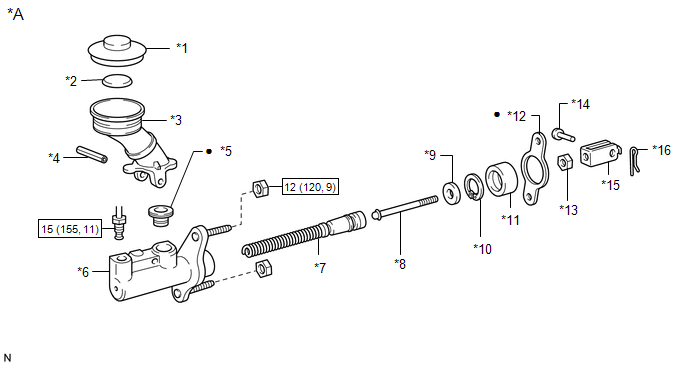
| *A | Example | - | - |
| *1 | FILTER CAP | *2 | FLOAT |
| *3 | RESERVOIR TANK | *4 | SLOTTED SPRING PIN |
| *5 | GROMMET | *6 | CYLINDER |
| *7 | PISTON | *8 | PUSH ROD |
| *9 | WASHER | *10 | SNAP RING |
| *11 | BOOT | *12 | GASKET |
| *13 | LOCK NUT | *14 | CLEVIS PIN |
| *15 | CLEVIS | *16 | CLIP |
 | N*m (kgf*cm, ft.*lbf): Specified torque | ● | Non-reusable part |
(c) Torque specifications, grease application areas and non-reusable parts are emphasized in the procedures.
HINT:
There are cases where such information can only be explained by using an illustration. In these cases, torque, oil and other information are described in the illustration.
(d) Only items with key points are described in the text. What to do and other details are explained using illustrations next to the text. Both the text and illustrations are accompanied by standard values and notices.
| Illustration | What to do and where to do it |
| Task heading | What work will be performed |
| Explanation text |
|
(e) Illustrations of similar vehicle models are sometimes used. In these cases, minor details may be different from the actual vehicle.
(f) Procedures are presented in a step-by-step format.
SERVICE SPECIFICATIONS
(a) Specifications are presented in boldface text throughout the manual. The specifications are also found in the "Specifications" section for reference.
TERM DEFINITIONS
| CAUTION | Possibility of injury to you or other people. |
| NOTICE | Possibility of damage to components being repaired. |
| HINT | Provides additional information to help you perform repairs. |
INTERNATIONAL SYSTEM OF UNITS
(a) The units used in this manual comply with the International System of Units (SI UNIT) standard. Other units from the metric system and the English systems are also provided.
- Example:
Torque:
30 N·m {306 kgf·cm, 22 ft·lbf}
 How To Proceed With Troubleshooting
HOW TO PROCEED WITH TROUBLESHOOTING OPERATION FLOW HINT: Perform troubleshooting in accordance with the procedure below. The following is an outline of basic troubleshooting procedure. Confirm the tro ...
 Identification Information
Vehicle Identification And Serial NumbersVEHICLE IDENTIFICATION AND SERIAL NUMBERS VEHICLE IDENTIFICATION NUMBER (a) The vehicle identification number is stamped on the vehicle body and on the certifi ...
Other materials:
Lexus RX (RX 350L, RX450h) 2016-2026 Repair Manual > Height Control Sensor: Components
COMPONENTS ILLUSTRATION *1 REAR HEIGHT CONTROL SENSOR SUB-ASSEMBLY - - N*m (kgf*cm, ft.*lbf): Specified torque - - ...
Lexus RX (RX 350L, RX450h) 2016-2026 Repair Manual > Lighting System (w/ Automatic Headlight Beam Level Control System): Turn Signal Light Circuit
DESCRIPTION The combination meter assembly controls the illumination and turning off of the rear turn signal lights. WIRING DIAGRAM PROCEDURE 1. CHECK OPERATION (REAR TURN SIGNAL LIGHTS) (a) Check the operation of the rear turn signal lights. Result Proceed to LH side rear turn si ...
Lexus RX (RX 350L, RX450h) 2016-{YEAR} Owners Manual
- For your information
- Pictorial index
- For safety and security
- Instrument cluster
- Operation of each component
- Driving
- Lexus Display Audio system
- Interior features
- Maintenance and care
- When trouble arises
- Vehicle specifications
- For owners
Lexus RX (RX 350L, RX450h) 2016-{YEAR} Repair Manual

0.0091