Lexus RX (RX 350L, RX450h) 2016-2026 Repair Manual: Installation
INSTALLATION
PROCEDURE
1. INSTALL FUEL SUCTION TUBE WITH PUMP AND GAUGE ASSEMBLY
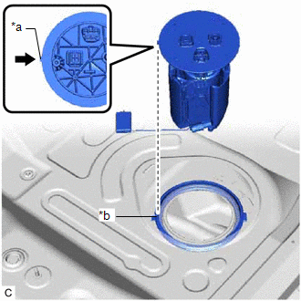
(a) Install a new fuel suction tube set gasket to the fuel tank assembly.
| (b) Set the fuel suction tube with pump and gauge assembly to the fuel tank assembly. NOTICE: Be careful not to bend the arm of the fuel sender gauge assembly. HINT: Align the protrusion of the fuel suction tube with pump and gauge assembly with the notch of the tank suction tube support. |
|
2. INSTALL FUEL PUMP GAUGE RETAINER
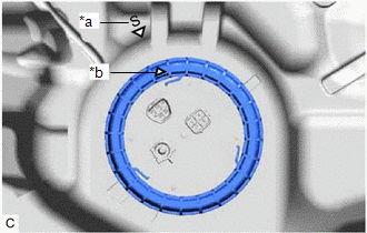
| (a) Align the triangle mark on new fuel pump gauge retainer with the "S" mark on the fuel tank assembly while pushing down the fuel suction tube with pump and gauge assembly, attach the fuel pump gauge retainer. |
|
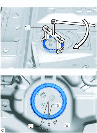
(b) Install SST (fuel pump retainer tool assy) to the fuel pump gauge retainer.
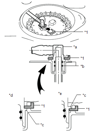
(1) Insert 2 SST (claw) between the service hole and fuel pump gauge retainer, and adjust the position so that the protrusions of the fuel pump gauge retainer are aligned with the grooves of SST (claw) as shown in the illustration.
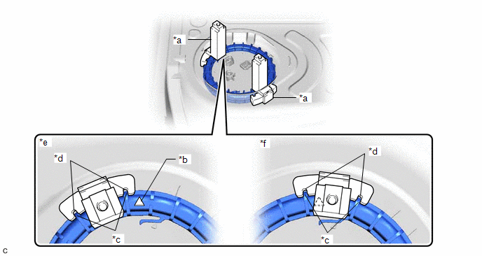
| *a | SST (Claw) | *b | Triangle Mark |
| *c | Protrusion of Fuel Pump Gauge Retainer | *d | Groove of SST (Claw) |
| *e | Correct | *f | Incorrect |
SST: 09808-14040
09882-14040
NOTICE:
Ensure that SST (claw) does not cover the triangle mark of the fuel pump gauge retainer.
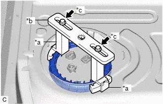
| (2) While ensuring that SST (plate) is centered, install SST (plate) to 2 SST (claw) with 2 SST (bolt and washer set). SST: 09808-14040 09881-14040 09883-14040 |
|
| (c) While lightly pushing down on SST (fuel pump retainer tool assy), tighten the fuel pump gauge retainer by 1 and a half turns so that the triangle mark on the fuel pump gauge retainer is positioned between the "MAX" and "A" marks on the fuel tank assembly. NOTICE:
HINT: While pushing down on SST (fuel pump retainer tool assy), turn the fuel pump gauge retainer clockwise to tighten. Make sure that the detent of the tank suction tube support does not move out of the groove of the fuel tank assembly. |
|
3. CONNECT FUEL TANK MAIN TUBE SUB-ASSEMBLY
| (a) Push the fuel tube joint onto the plug of the fuel suction plate sub-assembly, then install the tube joint clip. NOTICE:
|
|
4. CHECK AIRTIGHTNESS
| (a) After installing the fuel suction tube with pump and gauge assembly, check for fuel leaks by first applying soapy water to the area where the fuel suction plate sub-assembly and fuel pump gauge retainer contact, and then blow forcibly into the fuel inlet area through a flexible pouring spout or similar tube. |
|
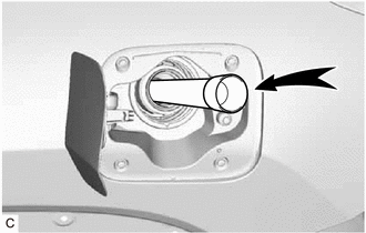
(b) Blow forcibly until the reverse flow prevention valve inside the fuel inlet activates.
NOTICE:
Be careful not to inhale any fuel vapor.
HINT:
There should be a faintly audible sound when the reverse flow prevention valve operates.
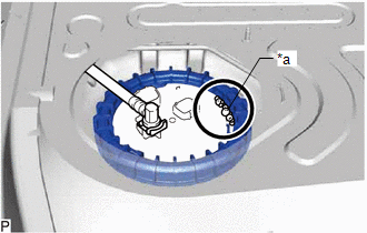
| (c) Check that the contact areas of the fuel suction tube with pump and gauge assembly, etc. has resulted in a condition where fuel will leak, air will leak out as shown in the illustration. NOTICE: If air leaks out, recheck the installation condition, and replace the fuel pump gauge retainer and fuel suction tube set gasket with new ones. Also, make sure to fully wipe away the soapy water. (Any remaining soapy water can cause the fuel suction tube set gasket to slip and result in an improper seal.) |
|
5. INSTALL REAR FLOOR SERVICE HOLE COVER
(a) Remove any remaining butyl tape from the rear floor service hole cover and vehicle body.
(b) Clean the installation surfaces of the rear floor service hole cover and vehicle body.
(c) Connect the 2 fuel pump connectors.
(d) Install the rear floor service hole cover with new butyl tape.
(e) w/ Rear No. 2 Seat:
(1) Return the rear No. 2 floor silencer to its original position.
(2) Return the rear floor silencer to its original position.
(3) Install the rear No. 1 floor silencer pad and No. 2 floor silencer pad to the vehicle body with the 2 No. 3 dash panel insulator plates.
| (4) Return the front floor carpet assembly to its original position as shown in the illustration. |
|
(f) w/o Rear No. 2 Seat:
(1) Return the rear floor silencer to its original position.
(2) Return the front floor carpet assembly to its original position and install the 3 clips.
6. CONNECT CABLE TO NEGATIVE BATTERY TERMINAL
NOTICE:
When disconnecting the cable, some systems need to be initialized after the cable is reconnected.
Click here .gif)
7. INSPECT FOR FUEL LEAK
Click here
8. INSTALL REAR SEAT SIDE GARNISH LH
-
w/ Rear No. 2 Seat:
Click here
-
w/o Rear No. 2 Seat:
Click here
9. INSTALL FRONT DECK SIDE TRIM COVER LH (w/ Rear No. 2 Seat)
Click here
10. INSTALL UPPER QUARTER TRIM PAD LH (w/o Rear No. 2 Seat)
Click here
11. INSTALL REAR SEAT SIDE GARNISH RH
HINT:
Use the same procedure as for the LH side.
12. INSTALL FRONT DECK SIDE TRIM COVER RH (w/ Rear No. 2 Seat)
HINT:
Use the same procedure as for the LH side.
13. INSTALL UPPER QUARTER TRIM PAD RH (w/o Rear No. 2 Seat)
HINT:
Use the same procedure as for the LH side.
14. INSTALL REAR SEAT ASSEMBLY LH (w/o Rear No. 2 Seat)
Click here
15. INSTALL REAR SEAT ASSEMBLY RH (w/o Rear No. 2 Seat)
Click here
16. INSTALL REAR NO. 1 SEAT ASSEMBLY (w/ Rear No. 2 Seat)
-
for Captain Seat Type:
Click here
-
for 60/40 Split Seat Type LH Side:
Click here
-
for 60/40 Split Seat Type RH Side:
Click here
17. INSTALL REAR DOOR SCUFF PLATE LH
-
w/ Rear No. 2 Seat:
Click here
-
w/o Rear No. 2 Seat:
Click here
18. INSTALL REAR DOOR INSIDE SCUFF PLATE LH (w/ Rear No. 2 Seat)
Click here
19. INSTALL REAR DOOR SCUFF PLATE RH
HINT:
Use the same procedure as for the LH side.
20. INSTALL REAR DOOR INSIDE SCUFF PLATE RH (w/ Rear No. 2 Seat)
HINT:
Use the same procedure as for the LH side.
21. INSTALL REAR NO. 2 SEAT ASSEMBLY (w/ Rear No. 2 Seat)
Click here
22. PERFORM INITIALIZATION
(a) Perform "Inspection After Repair" after replacing the fuel pump.
Click here
 Removal
REMOVAL CAUTION / NOTICE / HINT The necessary procedures (adjustment, calibration, initialization or registration) that must be performed after parts are removed and installed, or replaced during fuel ...

Other materials:
Lexus RX (RX 350L, RX450h) 2016-2026 Repair Manual > Refrigerant (for Hfo-1234yf(r1234yf)): Precaution
PRECAUTION PRECAUTIONS FOR REFRIGERANT HFO-1234yf (R1234yf) (a) Compatibility (1) The parts used in the refrigerant cycle, the compressor oil, etc. of an HFO-1234yf (R1234yf) system are not compatible with a conventional HFC-134a (R134a) system. (b) HFO-1234yf (R1234yf) Refrigerant (1) Always use HF ...
Lexus RX (RX 350L, RX450h) 2016-2026 Repair Manual > Window Defogger System: Terminals Of Ecu
TERMINALS OF ECU CHECK AIR CONDITIONING AMPLIFIER ASSEMBLY *A w/o Seat Heater System *B w/ Seat Heater System (a) Disconnect the J43 air conditioning amplifier assembly connector. (b) Measure the voltage and resistance according to the value(s) in the table below. HINT: Measure the valu ...
Lexus RX (RX 350L, RX450h) 2016-{YEAR} Owners Manual
- For your information
- Pictorial index
- For safety and security
- Instrument cluster
- Operation of each component
- Driving
- Lexus Display Audio system
- Interior features
- Maintenance and care
- When trouble arises
- Vehicle specifications
- For owners
Lexus RX (RX 350L, RX450h) 2016-{YEAR} Repair Manual

0.0153