Lexus RX (RX 350L, RX450h) 2016-2026 Repair Manual: Removal
REMOVAL
CAUTION / NOTICE / HINT
The necessary procedures (adjustment, calibration, initialization or registration) that must be performed after parts are removed and installed, or replaced during fuel pump removal/installation are shown below.
Necessary Procedures After Parts Removed/Installed/Replaced| Replaced Part or Performed Procedure | Necessary Procedure | Effect/Inoperative Function when Necessary Procedure not Performed | Link |
|---|---|---|---|
|
*1: When performing learning using the Techstream.
Click here | |||
| Battery terminal is disconnected/reconnected | Memorize steering angle neutral point | Lane Control System | |
| Pre-collision system | |||
| Intelligent clearance sonar system*1 | |||
| Lighting system (w/ Automatic Headlight Beam Level Control System) | | ||
| Parking assist monitor system | | ||
| Panoramic view monitor system | | ||
| Initialize back door lock | Power door lock control system | | |
| Reset back door close position | Power Back Door System (w/ Outside Door Control Switch) | | |
| Replacement of fuel pump | Inspection After Repair |
| |
PROCEDURE
1. PRECAUTION
NOTICE:
After turning the engine switch off, waiting time may be required before disconnecting the cable from the negative (-) battery terminal. Therefore, make sure to read the disconnecting the cable from the negative (-) battery terminal notices before proceeding with work.
Click here .gif)
2. DISCHARGE FUEL SYSTEM PRESSURE
Click here
3. DISCONNECT CABLE FROM NEGATIVE BATTERY TERMINAL
NOTICE:
When disconnecting the cable, some systems need to be initialized after the cable is reconnected.
Click here
4. REMOVE REAR NO. 2 SEAT ASSEMBLY (w/ Rear No. 2 Seat)
Click here
5. REMOVE REAR DOOR INSIDE SCUFF PLATE LH (w/ Rear No. 2 Seat)
Click here
6. REMOVE REAR DOOR SCUFF PLATE LH
-
w/ Rear No. 2 Seat:
Click here
-
w/o Rear No. 2 Seat:
Click here
7. REMOVE REAR DOOR INSIDE SCUFF PLATE RH (w/ Rear No. 2 Seat)
HINT:
Use the same procedure as for the LH side.
8. REMOVE REAR DOOR SCUFF PLATE RH
HINT:
Use the same procedure as for the LH side.
9. REMOVE REAR NO. 1 SEAT ASSEMBLY (w/ Rear No. 2 Seat)
-
for Captain Seat Type:
Click here
-
for 60/40 Split Seat Type LH Side:
Click here
-
for 60/40 Split Seat Type RH Side:
Click here
10. REMOVE REAR SEAT ASSEMBLY LH (w/o Rear No. 2 Seat)
Click here
11. REMOVE REAR SEAT ASSEMBLY RH (w/o Rear No. 2 Seat)
Click here
12. REMOVE UPPER QUARTER TRIM PAD LH (w/o Rear No. 2 Seat)
Click here
13. REMOVE FRONT DECK SIDE TRIM COVER LH (w/ Rear No. 2 Seat)
Click here
14. REMOVE REAR SEAT SIDE GARNISH LH
-
w/ Rear No. 2 Seat:
Click here
-
w/o Rear No. 2 Seat:
Click here
15. REMOVE UPPER QUARTER TRIM PAD RH (w/o Rear No. 2 Seat)
HINT:
Use the same procedure as for the LH side.
16. REMOVE FRONT DECK SIDE TRIM COVER RH (w/ Rear No. 2 Seat)
HINT:
Use the same procedure as for the LH side.
17. REMOVE REAR SEAT SIDE GARNISH RH
HINT:
Use the same procedure as for the LH side.
18. REMOVE REAR FLOOR SERVICE HOLE COVER
(a) w/ Rear No. 2 Seat:
| (1) Turn back the front floor carpet assembly. |
|
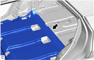
| (2) Remove the 2 No. 3 dash panel insulator plates, rear No. 1 floor silencer pad and No. 2 floor silencer pad from the vehicle body. |
|
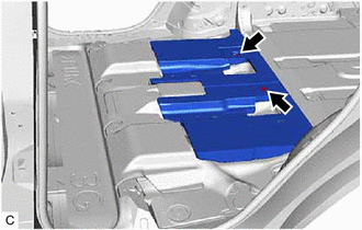
| (3) Turn back the rear floor silencer. |
|
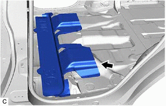
| (4) Turn back the rear No. 2 floor silencer. |
|
(b) w/o Rear No. 2 Seat:
| (1) Remove the 3 clips and turn back the front floor carpet assembly. |
|

| (2) Turn back the rear floor silencer. |
|
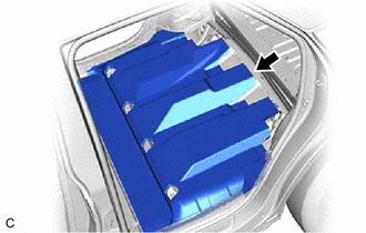
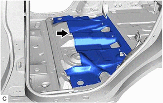
| (c) Using a clip remover with its tip wrapped with protective tape, remove the rear floor service hole cover and butyl tape. |
|
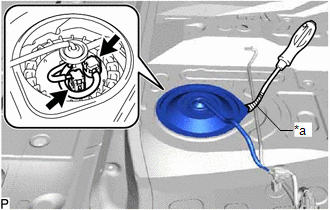
(d) Disconnect the 2 fuel pump connectors.
19. DISCONNECT FUEL TANK MAIN TUBE SUB-ASSEMBLY
(a) Remove the tube joint clip, and pull off the fuel tube joint of the fuel tank main tube sub-assembly.
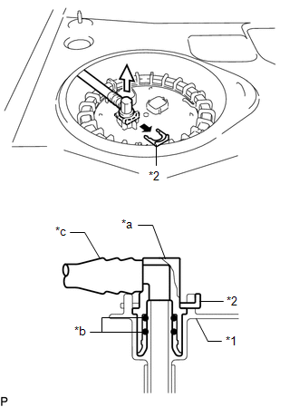
| *1 | Fuel Suction Plate Sub-assembly |
| *2 | Tube Joint Clip |
| *a | Fuel Tube Joint |
| *b | O-ring |
| *c | Nylon Tube |
.png) | Pull off |
.png) | Pull off |
NOTICE:
- Remove any foreign matter on the fuel tube joint before performing this work.
- Do not scratch or allow any foreign matter to get on the parts when disconnecting them as the fuel tube connector has O-rings that seal the pipe (fuel pipe).
- Be sure to disconnect the fuel tube joint by hand.
- Do not bend, twist, pinch or kink the nylon tube.
- Cover the disconnected fuel tube joint with a plastic bag to prevent damage and contamination.
- If the fuel tube joint and fuel suction plate sub-assembly are stuck, push and pull to release them.
20. REMOVE FUEL PUMP GAUGE RETAINER
NOTICE:
Before performing these procedures, first cover the connectors and fuel tube joint of the fuel suction tube with pump and gauge assembly with vinyl tape and then clean any dirt and foreign matter in order to prevent contamination of the fuel system.
(a) Install SST (fuel pump holding tool assy) to the fuel pump gauge retainer.
(1) Insert SST (claw No. 1) between the service hole and fuel pump gauge retainer as shown in the illustration.
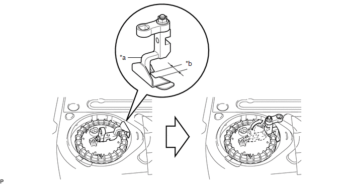
| *a | SST (Claw No. 1) | *b | Wide |
SST: 09808-14050
09882-14050
(2) Align the detent of the tank suction tube support and cutout of SST (claw No. 1).
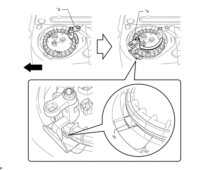
| *a | SST (Claw No. 1) | *b | Detent of Tank Suction Tube Support |
| | Front | - | - |
(3) Insert SST (claw) between the service hole and fuel pump gauge retainer as shown in the illustration.
| *a | SST (Claw No. 1) | *b | SST (Claw) |
SST: 09808-14040
09882-14040
(4) Insert SST (claw No. 2) between the service hole and fuel pump gauge retainer, and align it with the second detent of the tank suction tube support.
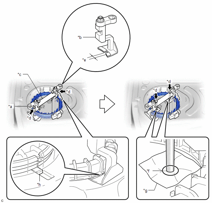
| *a | SST (Claw No. 1) | *b | SST (Claw No. 2) |
| *c | SST (Bridge) | *d | SST (Bolt) |
| *e | Narrow | *f | Contact |
| *g | Cloth | *h | Detent of Tank Suction Tube Support |
SST: 09808-14050
09881-14050
09882-14050
09883-14050
09884-14050
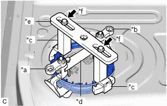
(5) Install SST (bridge) to SST (claw No. 1) and SST (claw No. 2) with 2 SST (bolt).
(6) Place a piece of cloth or equivalent on the fuel suction tube with pump and gauge assembly and lightly tighten 2 SST (bolt) of SST (bridge) until they come into contact with the fuel suction tube with pump and gauge assembly.
NOTICE:
If a piece of cloth or equivalent is not placed between the fuel suction tube with pump and gauge assembly and 2 SST (bolt), the fuel suction tube with pump and gauge assembly may be damaged.
(b) Install SST (fuel pump retainer tool assy) to the fuel pump gauge retainer.
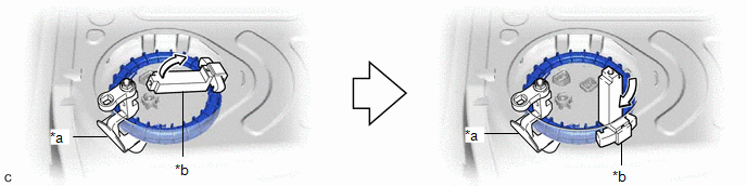
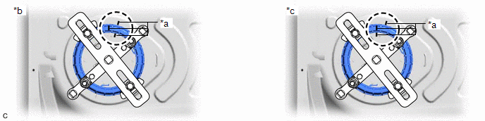
(1) Position SST (claw) next to SST (claw No. 1) so that the protrusions of the fuel pump gauge retainer are aligned with the grooves of SST (claw). Insert the second SST (claw) between the service hole and fuel pump gauge retainer, and position it next to SST (claw No. 2) so that it is opposite to SST (claw), and the protrusions of the fuel pump gauge retainer are aligned with the grooves of SST (claw).
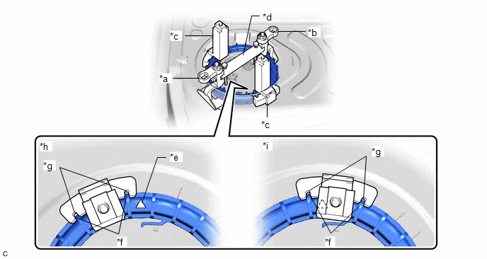
| *a | SST (Claw No. 1) | *b | SST (Claw No. 2) |
| *c | SST (Claw) | *d | SST (Bridge) |
| *e | Triangle Mark | *f | Protrusion of Fuel Pump Gauge Retainer |
| *g | Groove of SST (Claw) | *h | Correct |
| *i | Incorrect | - | - |
SST: 09808-14040
09882-14040
NOTICE:
Ensure that SST (claw) does not cover the triangle mark of the fuel pump gauge retainer.
| (2) While ensuring that SST (plate) is centered, install SST (plate) to 2 SST (claw) with 2 SST (bolt and washer set). SST: 09808-14040 09881-14040 09883-14040 |
|
| (c) Attach 2 breaker bars to SST (fuel pump holding tool assy) and 1 breaker bar to SST (fuel pump retainer tool assy). |
|
| (d) Place paint marks on the fuel suction tube with pump and gauge assembly, fuel pump gauge retainer and fuel tank assembly as shown in the illustration. |
|
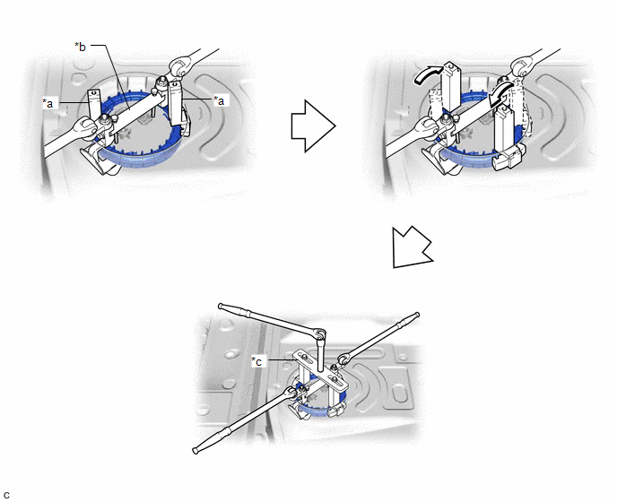
(e) While holding the 2 breaker bars attached to SST (fuel pump holding tool assy), turn the breaker bar attached to SST (fuel pump retainer tool assy) to loosen the fuel pump gauge retainer. [*1]
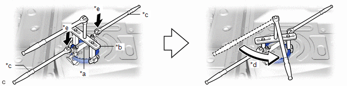
| *a | SST (Fuel Pump Holding Tool Assy) | *b | SST (Fuel Pump Retainer Tool Assy) |
| *c | Holding | *d | Turn |
| *e | Push down | - | - |
NOTICE:
Push down on the 2 locations shown in the illustration to prevent SST (fuel pump holding tool assy) from turning.
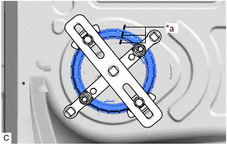
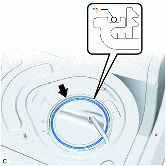
(f) Check that only the paint mark on the fuel pump gauge retainer has moved.
| *a | Paint Mark | *b | Correct |
| *c | Incorrect | - | - |
HINT:
If the paint mark on the fuel suction tube with pump and gauge assembly has also moved, tighten the fuel pump gauge retainer until the paint marks are aligned at the original position. Then repeat from step [*1].
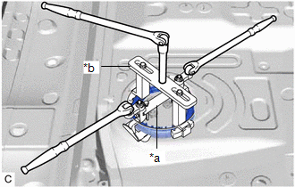
(g) Loosen the fuel pump gauge retainer by using SST (fuel pump retainer tool assy) until the fuel pump gauge retainer turns approximately 360°.
| *a | SST (Claw) | *b | SST (Fuel Pump Holding Tool Assy) |
| *c | SST (Fuel Pump Retainer Tool Assy) | - | - |
(h) Remove SST (fuel pump retainer tool assy) and SST (fuel pump holding tool assy) from the fuel pump gauge retainer.
(i) Check that the fuel pump gauge retainer can be loosened by hand.
HINT:
If the fuel pump gauge retainer cannot be loosened by hand, use SST (fuel pump retainer tool assy) to loosen the fuel pump gauge retainer.
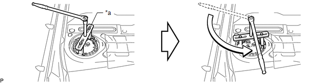
| *a | SST (Fuel Pump Retainer Tool Assy) | - | - |
SST: 09808-14040
09881-14040
09882-14040
09883-14040
(j) While holding the fuel suction tube with pump and gauge assembly by hand, remove the fuel pump gauge retainer.
21. REMOVE FUEL SUCTION TUBE WITH PUMP AND GAUGE ASSEMBLY
(a) Remove the fuel suction tube with pump and gauge assembly from the fuel tank assembly.
NOTICE:
Be careful not to bend the arm of the fuel sender gauge assembly.
| (b) Remove the fuel suction tube set gasket from the fuel tank assembly. |
|
 Reassembly
REASSEMBLY PROCEDURE 1. INSTALL FUEL PUMP HINT: Perform "Inspection After Repair" after replacing the fuel pump. Click here (a) Apply a light coat of gasoline to a new O-ring. Then install the O ...
 Installation
INSTALLATION PROCEDURE 1. INSTALL FUEL SUCTION TUBE WITH PUMP AND GAUGE ASSEMBLY (a) Install a new fuel suction tube set gasket to the fuel tank assembly. (b) Set the fuel suction tube with pump an ...
Other materials:
Lexus RX (RX 350L, RX450h) 2016-2026 Repair Manual > Wireless Charging System: System Description
SYSTEM DESCRIPTION WIRELESS CHARGER FUNCTION OUTLINE (a) The wireless charging system enables Qi-compatible* rechargeable devices, such as a cellular phone, to be recharged by merely placing it on the charging area of the mobile wireless charger cradle assembly. HINT: *: Qi (pronounced chee) is a wi ...
Lexus RX (RX 350L, RX450h) 2016-2026 Repair Manual > Oil Pressure Switch: Inspection
INSPECTION PROCEDURE 1. INSPECT ENGINE OIL PRESSURE SWITCH ASSEMBLY (a) Disconnect the wire harness protector. *1 Wire Harness Protector (b) Disconnect the engine oil pressure switch assembly connector. (c) Start the engine. (d) Measure the resistance according to the v ...
Lexus RX (RX 350L, RX450h) 2016-{YEAR} Owners Manual
- For your information
- Pictorial index
- For safety and security
- Instrument cluster
- Operation of each component
- Driving
- Lexus Display Audio system
- Interior features
- Maintenance and care
- When trouble arises
- Vehicle specifications
- For owners
Lexus RX (RX 350L, RX450h) 2016-{YEAR} Repair Manual

0.01