Lexus RX (RX 350L, RX450h) 2016-2026 Repair Manual: Removal
REMOVAL
CAUTION / NOTICE / HINT
The necessary procedures (adjustment, calibration, initialization or registration) that must be performed after parts are removed and installed, or replaced during fuel sender gauge assembly removal/installation are shown below.
Necessary Procedures After Parts Removed/Installed/Replaced| Replaced Part or Performed Procedure | Necessary Procedure | Effect/Inoperative Function when Necessary Procedure not Performed | Link |
|---|---|---|---|
|
*1: When performing learning using the Techstream.
Click here | |||
| Battery terminal is disconnected/reconnected | Memorize steering angle neutral point | Lane Control System | |
| Pre-collision system | |||
| Intelligent clearance sonar system*1 | |||
| Lighting system (w/ Automatic Headlight Beam Level Control System) | | ||
| Parking assist monitor system | | ||
| Panoramic view monitor system | | ||
| Initialize back door lock | Power door lock control system | | |
| Reset back door close position | Power Back Door System (w/ Outside Door Control Switch) | | |
PROCEDURE
1. REMOVE FUEL SUCTION TUBE WITH PUMP AND GAUGE ASSEMBLY
-
for TMC Made:
Click here
.gif)
-
for TMMC Made:
Click here
2. REMOVE FUEL SENDER GAUGE ASSEMBLY
(a) Disconnect the fuel sender gauge assembly connector.
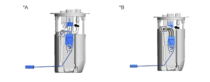
| *A | for TMC Made | *B | for TMMC Made |
(b) Disengage the clamp to disconnect the wire harness.
(c) Disengage the claw to remove the fuel sender gauge assembly from the fuel suction tube with pump and gauge assembly.
NOTICE:
- Do not touch the resistance plate or contacts of the fuel sender gauge assembly.
- Be careful not to bend the arm of the fuel sender gauge assembly.
 Components
COMPONENTS ILLUSTRATION *A for TMC Made - - *1 FUEL SENDER GAUGE ASSEMBLY *2 FUEL SUCTION TUBE WITH PUMP AND GAUGE ASSEMBLY ILLUSTRATION *A for TMMC Made - - *1 ...
 Inspection
INSPECTION PROCEDURE 1. INSPECT FUEL SENDER GAUGE ASSEMBLY (a) Check that the float moves smoothly between F and E. (b) Check the fuel sender gauge assembly voltage. (1) Apply 5 V between terminals ...
Other materials:
Lexus RX (RX 350L, RX450h) 2016-2026 Repair Manual > Lighting System (w/ Automatic Headlight Beam Level Control System): Turn Signal Switch Circuit
DESCRIPTION The combination meter assembly receives the turn signal switch information and controls the turn signal lights. WIRING DIAGRAM CAUTION / NOTICE / HINT NOTICE: When replacing the combination meter assembly, always replace it with a new one. If a combination meter assembly which was insta ...
Lexus RX (RX 350L, RX450h) 2016-2026 Repair Manual > Audio And Visual System (for 8 Inch Display): GPS Antenna Connection Malfunction(short) (B15C0,B15C1)
DESCRIPTION These DTCs are stored when a malfunction occurs in the navigation antenna assembly. DTC No. Detection Item DTC Detection Condition Trouble Area B15C0 GPS Antenna Connection Malfunction(short) GPS Antenna Connection Malfunction(short)
Navigation antenna assembly
An ...
Lexus RX (RX 350L, RX450h) 2016-{YEAR} Owners Manual
- For your information
- Pictorial index
- For safety and security
- Instrument cluster
- Operation of each component
- Driving
- Lexus Display Audio system
- Interior features
- Maintenance and care
- When trouble arises
- Vehicle specifications
- For owners
Lexus RX (RX 350L, RX450h) 2016-{YEAR} Repair Manual

0.0123