Lexus RX (RX 350L, RX450h) 2016-2026 Repair Manual: Removal
REMOVAL
CAUTION / NOTICE / HINT
The necessary procedures (adjustment, calibration, initialization or registration) that must be performed after parts are removed and installed, or replaced during fuel pump removal/installation are shown below.
Necessary Procedures After Parts Removed/Installed/Replaced| Replaced Part or Performed Procedure | Necessary Procedure | Effect/Inoperative Function when Necessary Procedure not Performed | Link |
|---|---|---|---|
|
*1: When performing learning using the Techstream.
Click here | |||
| Battery terminal is disconnected/reconnected | Memorize steering angle neutral point | Lane Control System | |
| Pre-collision system | |||
| Intelligent clearance sonar system*1 | |||
| Lighting system (w/ Automatic Headlight Beam Level Control System) | | ||
| Parking assist monitor system | | ||
| Panoramic view monitor system | | ||
| Initialize back door lock | Power door lock control system | | |
| Reset back door close position | Power Back Door System (w/ Outside Door Control Switch) | | |
| Rear wheel alignment adjustment |
|
| |
| Suspension, tires, etc. (The vehicle height changes because of suspension or tire replacement) |
|
| |
| Rear television camera assembly optical axis (Back camera position setting) | Parking assist monitor system | for Initialization: for Calibration: | |
| Panoramic view monitor system | for Initialization: for Calibration: | |
| Initialize headlight ECU sub-assembly LH |
| | |
| Rear height control sensor sub-assembly RH | Initialize headlight ECU sub-assembly LH |
| |
| Gas leak from exhaust system is repaired | Inspection After Repair |
| |
PROCEDURE
1. REMOVE FUEL SUCTION TUBE WITH PUMP AND GAUGE ASSEMBLY
-
for TMC Made:
Click here
.gif)
-
for TMMC Made:
Click here
2. DRAIN FUEL
3. REMOVE REAR SUSPENSION MEMBER SUB-ASSEMBLY (for 2WD)
Click here
4. REMOVE REAR SUSPENSION MEMBER SUB-ASSEMBLY (for AWD)
Click here
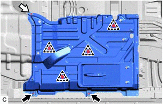
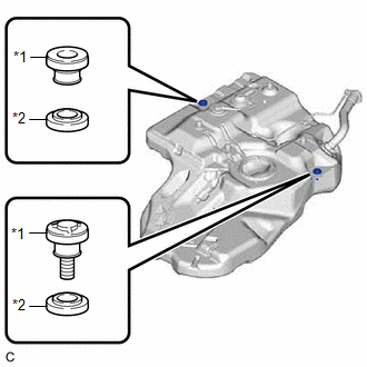
5. REMOVE FRONT CENTER FLOOR COVER (for TMC Made)
(a) Remove the 2 screws and nut.
.png) | Screw |
.png) | Nut |
(b) Disengage the 4 clips to remove the front center floor cover.
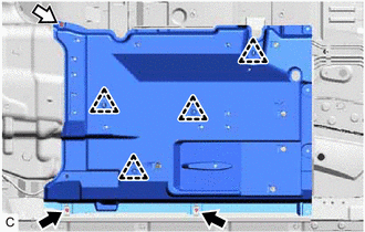
6. REMOVE FRONT CENTER FLOOR COVER (for TMMC Made)
(a) Remove the 2 screws and nut.
| | Screw |
| | Nut |
(b) Disengage the 4 clips to remove the front center floor cover.
7. REMOVE CHARCOAL CANISTER PROTECTOR
Click here
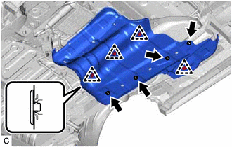
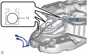
8. REMOVE NO. 1 FUEL TANK PROTECTOR SUB-ASSEMBLY
| (a) Remove the 4 clips, 4 nuts and No. 1 fuel tank protector sub-assembly. |
|
9. DISCONNECT FUEL TANK MAIN TUBE SUB-ASSEMBLY
| (a) Disconnect the fuel tank main tube sub-assembly from the fuel pipe. Click here |
|
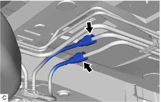
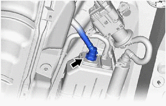
10. DISCONNECT FUEL TANK BREATHER TUBE
| (a) Disconnect the fuel tank breather tube from the fuel pipe. Click here |
|
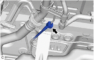
11. DISCONNECT FUEL TANK VENT HOSE SUB-ASSEMBLY
| (a) Disconnect the fuel tank vent hose sub-assembly from the charcoal canister assembly. Click here |
|
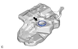
12. DISCONNECT FUEL TANK TO FILLER PIPE HOSE
(a) Pull out the retainer to disengage the lock claws and pull off the fuel tank to filler pipe hose from the fuel tank filler pipe assembly.
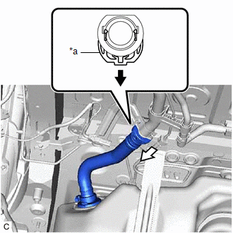
| *a | Retainer |
| | Pull out |
| | Pull out |
NOTICE:
- Do not scratch or allow any foreign matter to get on the parts when disconnecting them as the fuel tank to filler pipe hose connector has an O-ring that seals the fuel tank filler pipe assembly.
- Be sure to disconnect the fuel tank to filler pipe hose connector by hand.
- Do not bend, twist, pinch or kink the fuel tank to filler pipe hose.
- Cover the disconnected fuel tank to filler pipe hose with a plastic bag to prevent damage and contamination.
- If the fuel tank to filler pipe hose connector and fuel tank filler pipe assembly are stuck, push and pull to release them.
13. REMOVE FUEL TANK ASSEMBLY
CAUTION:
The fuel tank assembly is very heavy. Be sure to follow the procedure described in the repair manual, or the fuel tank assembly may fall off the engine lifter.
.png)
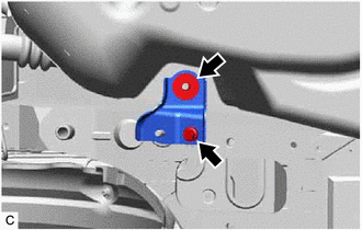
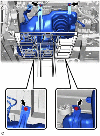
| (a) Remove the bolt, nut and rear fuel tank bracket LH. |
|
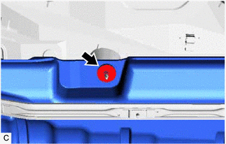
| (b) Remove the nut. |
|
| (c) Support the fuel tank assembly using an engine lifter. HINT: Using height adjustment attachments and plate lift attachments, keep the fuel tank assembly horizontal. |
|
(d) Remove the 4 bolts, No. 1 fuel tank band sub-assembly LH and No. 1 fuel tank band sub-assembly RH.
(e) Lower the engine lifter to remove the fuel tank assembly.
NOTICE:
- Be careful not to drop the fuel tank assembly.
- When removing the fuel tank assembly, tilt it slightly to prevent it from interfering with the surrounding parts.
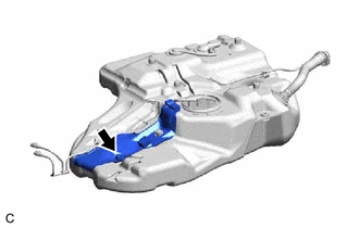
14. REMOVE REAR FUEL TANK SIDE PLATE (for TMC Made)
| (a) Remove the fuel tank cushion and rear fuel tank side plate from the fuel tank assembly. |
|
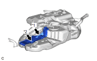
15. REMOVE REAR FUEL TANK SIDE PLATE (for TMMC Made)
| (a) Remove the fuel tank band pin, fuel tank cushion and fuel tank side plate from the fuel tank assembly. |
|
16. REMOVE FUEL TANK MAIN TUBE SUB-ASSEMBLY
| (a) Disengage the 3 claws to remove the fuel tank main tube sub-assembly from the fuel tank assembly. |
|
17. REMOVE FUEL TANK CUSHION SET
| (a) Remove the 2 fuel tank cushion sets and 2 No. 5 fuel tank cushions from the fuel tank assembly. |
|
18. REMOVE TANK SUCTION TUBE SUPPORT
| (a) Remove the tank suction tube support from the fuel tank assembly. |
|
 Installation
INSTALLATION PROCEDURE 1. INSTALL TANK SUCTION TUBE SUPPORT (a) Install a new tank suction tube support to the fuel tank assembly. HINT: Align the protrusions of the tank suction tube support with ...

Other materials:
Lexus RX (RX 350L, RX450h) 2016-2026 Repair Manual > Cylinder Block: Disassembly
DISASSEMBLY CAUTION / NOTICE / HINT The necessary procedures (adjustment, calibration, initialization, or registration) that must be performed after parts are removed and installed, or replaced during engine unit removal/installation are shown below. Necessary Procedure After Parts Removed/Installed ...
Lexus RX (RX 350L, RX450h) 2016-2026 Owners Manual > Adjusting the steering wheel and mirrors: Inside rear view mirror
The rear view mirror's position can be adjusted to enable sufficient
confirmation
of the rear view.
Adjusting the height of rear view mirror
The height of the rear view mirror can be adjusted to suit your driving
posture.
Adjust the height of the rear view mirror
by moving it up and down. ...
Lexus RX (RX 350L, RX450h) 2016-{YEAR} Owners Manual
- For your information
- Pictorial index
- For safety and security
- Instrument cluster
- Operation of each component
- Driving
- Lexus Display Audio system
- Interior features
- Maintenance and care
- When trouble arises
- Vehicle specifications
- For owners
Lexus RX (RX 350L, RX450h) 2016-{YEAR} Repair Manual

0.0114