Lexus RX (RX 350L, RX450h) 2016-2026 Repair Manual: Installation
INSTALLATION
PROCEDURE
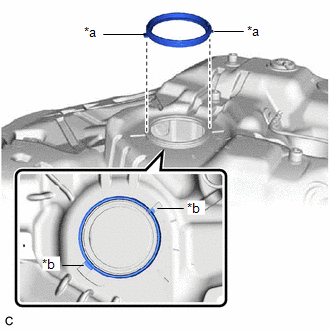
1. INSTALL TANK SUCTION TUBE SUPPORT
| (a) Install a new tank suction tube support to the fuel tank assembly. HINT: Align the protrusions of the tank suction tube support with the notches of the fuel tank assembly. |
|
2. INSTALL FUEL TANK CUSHION SET
(a) Install the 2 fuel tank cushion sets and 2 No. 5 fuel tank cushions to the fuel tank assembly.
3. INSTALL FUEL TANK MAIN TUBE SUB-ASSEMBLY
(a) Engage the 3 claws to install the fuel tank main tube sub-assembly to the fuel tank assembly.
4. INSTALL REAR FUEL TANK SIDE PLATE (for TMC Made)
(a) Install a new rear fuel tank side plate to the fuel tank assembly with the fuel tank cushion.
5. INSTALL REAR FUEL TANK SIDE PLATE (for TMMC Made)
(a) Install a new rear fuel tank side plate to the fuel tank assembly with the fuel tank cushion and fuel tank band pin.
6. INSTALL FUEL TANK ASSEMBLY
CAUTION:
The fuel tank assembly is very heavy. Be sure to follow the procedure described in the repair manual, or the fuel tank assembly may fall off the engine lifter.
.png)
(a) Set the fuel tank assembly on an engine lifter.
HINT:
Using height adjustment attachments and plate lift attachments, keep the fuel tank assembly horizontal.
(b) Using the engine lifter, slowly raise the fuel tank assembly, and then install the fuel tank assembly, No. 1 fuel tank band sub-assembly LH and No. 1 fuel tank band sub-assembly RH with the 4 bolts.
Torque:
for TMC Made :
45 N·m {459 kgf·cm, 33 ft·lbf}
for TMMC Made :
39.2 N·m {400 kgf·cm, 29 ft·lbf}
NOTICE:
- Be careful not to drop the fuel tank assembly.
- When installing the fuel tank assembly, tilt it slightly to prevent it from interfering with the surrounding parts.
(c) Install the rear fuel tank bracket LH with the bolt and nut.
Torque:
Bolt (for TMC Made) :
45 N·m {459 kgf·cm, 33 ft·lbf}
Bolt (for TMMC Made) :
39.2 N·m {400 kgf·cm, 29 ft·lbf}
Nut :
19.6 N·m {200 kgf·cm, 14 ft·lbf}
(d) Install the nut.
Torque:
19.6 N·m {200 kgf·cm, 14 ft·lbf}
7. CONNECT FUEL TANK TO FILLER PIPE HOSE
(a) Push the fuel tank to filler pipe hose to the fuel tank filler pipe assembly and push in the retainer to engage the lock claws.
NOTICE:
- Check that there are no scratches or foreign matter around the connected parts of the fuel tank to filler pipe hose connector and fuel tank filler pipe assembly before performing this work.
- After connecting the fuel tank to filler pipe hose, check that the fuel tank to filler pipe hose is securely connected by pulling on the fuel tank to filler pipe hose connector.
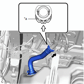
| *a | Retainer |
.png) | Push |
.png) | Push in |
8. CONNECT FUEL TANK VENT HOSE SUB-ASSEMBLY
(a) Connect the fuel tank vent hose sub-assembly to the charcoal canister assembly.
Click here .gif)
9. CONNECT FUEL TANK BREATHER TUBE
(a) Connect the fuel tank breather tube to the fuel pipe.
Click here
10. CONNECT FUEL TANK MAIN TUBE SUB-ASSEMBLY
(a) Connect the fuel tank main tube sub-assembly to the fuel pipe.
Click here
11. INSTALL NO. 1 FUEL TANK PROTECTOR SUB-ASSEMBLY
(a) Install the No. 1 fuel tank protector sub-assembly with the 4 nuts and 4 new clips.
Torque:
5.5 N·m {56 kgf·cm, 49 in·lbf}
12. INSTALL CHARCOAL CANISTER PROTECTOR
Click here
13. INSTALL FRONT CENTER FLOOR COVER
(a) Engage the 4 clips to install the front center floor cover.
(b) Install the 2 screws and nut.
14. INSTALL REAR SUSPENSION MEMBER SUB-ASSEMBLY (for 2WD)
Click here
15. INSTALL REAR SUSPENSION MEMBER SUB-ASSEMBLY (for AWD)
Click here
16. INSTALL FUEL SUCTION TUBE WITH PUMP AND GAUGE ASSEMBLY
-
for TMC Made:
Click here
-
for TMMC Made:
Click here
17. ADD FUEL
 Components
COMPONENTS ILLUSTRATION *A for TMC Made - - *1 FUEL TANK CUSHION SET *2 NO. 5 FUEL TANK CUSHION *3 REAR FUEL TANK BRACKET LH *4 NO. 1 FUEL TANK BAND SUB-ASSEMBLY RH * ...
 Removal
REMOVAL CAUTION / NOTICE / HINT The necessary procedures (adjustment, calibration, initialization or registration) that must be performed after parts are removed and installed, or replaced during fuel ...
Other materials:
Lexus RX (RX 350L, RX450h) 2016-2026 Repair Manual > Seat Heater Switch (for Front Side): Inspection
INSPECTION PROCEDURE 1. INSPECT REFRESHING SEAT SWITCH (for Front Side) (a) Apply battery voltage and check the operation of the switch according to the table below. OK: Battery Connection Condition Specified Condition Battery positive (+) → Terminal 3 Battery negative (-) → Termi ...
Lexus RX (RX 350L, RX450h) 2016-2026 Repair Manual > Dynamic Radar Cruise Control System: Brake Switch "A" Circuit Open (P057113)
DESCRIPTION When the brakes are applied by the dynamic radar cruise control system, the skid control ECU (brake actuator assembly) operates the stop light switch assembly (stop light control relay) to illuminate the stop lights. If the ECM receives a signal from the skid control ECU (brake actuator ...
Lexus RX (RX 350L, RX450h) 2016-{YEAR} Owners Manual
- For your information
- Pictorial index
- For safety and security
- Instrument cluster
- Operation of each component
- Driving
- Lexus Display Audio system
- Interior features
- Maintenance and care
- When trouble arises
- Vehicle specifications
- For owners
Lexus RX (RX 350L, RX450h) 2016-{YEAR} Repair Manual

0.0097