Lexus RX (RX 350L, RX450h) 2016-2026 Repair Manual: On-vehicle Inspection
ON-VEHICLE INSPECTION
CAUTION / NOTICE / HINT
The necessary procedures (adjustment, calibration, initialization or registration) that must be performed after parts are removed and installed, or replaced when repairing air leaks in the intake system are shown below.
Necessary Procedures After Parts Removed/Installed/Replaced| Replaced Part or Performed Procedure | Necessary Procedure | Effect/Inoperative Function when Necessary Procedure not Performed | Link |
|---|---|---|---|
| Air leak from intake system is repaired | Inspection After Repair |
| |
PROCEDURE
1. INSPECT INTAKE SYSTEM
CAUTION:
To prevent injury due to contact with an operating V-ribbed belt or cooling fan, keep your hands and clothing away from the V-ribbed belt and cooling fans when working in the engine compartment with the engine running or the engine switch on (IG).
.png)
(a) Check that there are no vacuum leaks at the points shown in the illustration.
HINT:
Perform Inspection After Repair after repairing vacuum leaks in the intake system.
Click here .gif)
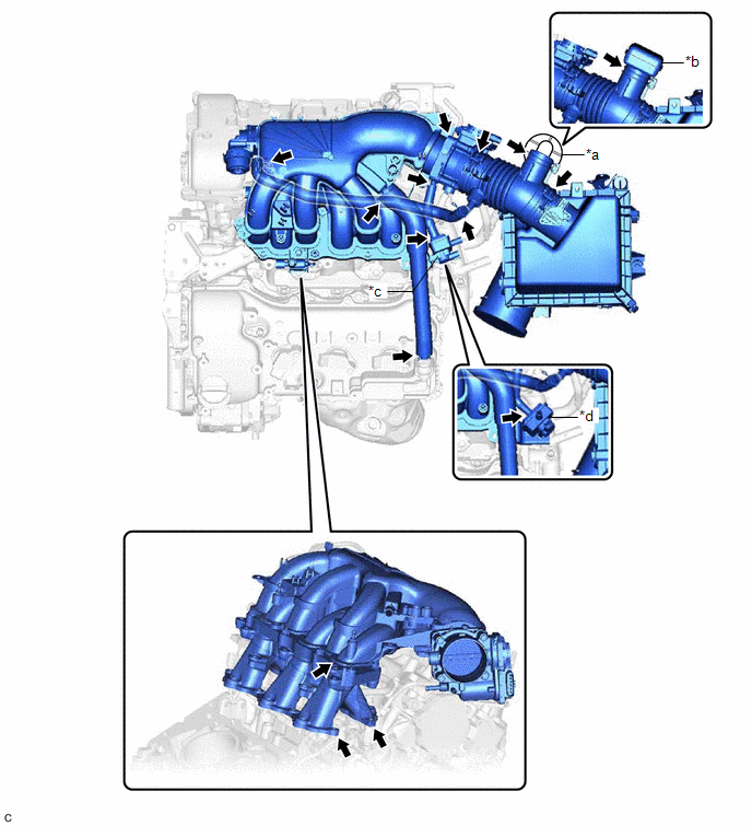
| *a | for Intake Air Sound Creator | *b | for Intake Air Resonator |
| *c | for TMMC Made | *d | except TMMC Made |
2. INSPECT INTAKE AIR CONTROL VALVE (for ACIS)
(a) Connect the GTS to the DLC3.
(b) Turn the engine switch on (IG).
(c) Turn the GTS on.
| (d) Enter the following menus: Powertrain / Engine / Active Test / Activate the VSV for Intake Control. Powertrain > Engine > Active Test
|
|
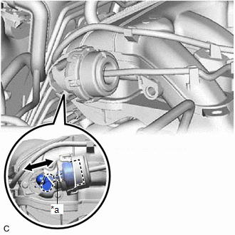
(e) When Activate the VSV for Intake Control is set to on, check that the actuator rod operates.
If the actuator rod does not operate, inspect the intake air control valve (for ACIS) and No. 1 vacuum switching valve assembly (for ACIS).
-
Inspect intake air control valve (for ACIS)
Click here
-
Inspect No. 1 vacuum switching valve assembly (for ACIS)
Click here
(f) When Activate the VSV for Intake Control is set to off, check that the actuator rod returns to its original position.
If the actuator rod does not return to its original position, inspect the intake air control valve (for ACIS) and No. 1 vacuum switching valve assembly (for ACIS).
-
Inspect intake air control valve (for ACIS)
Click here
-
Inspect No. 1 vacuum switching valve assembly (for ACIS)
Click here
3. PERFORM INITIALIZATION
(a) Perform Inspection After Repair after repairing vacuum leaks in the intake system.
Click here
 System Diagram
SYSTEM DIAGRAM *1 Throttle Body with Motor Assembly *2 Intake Air Control Valve (for ACIS) *3 Intake Air Control Valve Actuator (for ACIS) *4 ECM *5 Vacuum Switching Valve (f ...

Other materials:
Lexus RX (RX 350L, RX450h) 2016-2026 Repair Manual > Intelligent Clearance Sonar System: Steering Angle Midpoint Initial Setting Incomplete (C1AEA)
DESCRIPTION When the clearance warning ECU assembly detects that the steering angle neutral point memorization is incomplete during self diagnosis, C1AEA is stored. DTC No. Detection Item DTC Detection Condition Trouble Area C1AEA Steering Angle Midpoint Initial Setting Incomplete S ...
Lexus RX (RX 350L, RX450h) 2016-2026 Repair Manual > Front Power Seat Control System (w/ Memory): Slide Sensor Malfunction (B2650)
DESCRIPTION When the position control ECU and switch assembly LH does not receive a slide motor position sensor signal despite the seat having been moved forward or backward by power seat motor operation, this DTC is stored. DTC No. Detection Item DTC Detection Condition Trouble Area B2 ...
Lexus RX (RX 350L, RX450h) 2016-{YEAR} Owners Manual
- For your information
- Pictorial index
- For safety and security
- Instrument cluster
- Operation of each component
- Driving
- Lexus Display Audio system
- Interior features
- Maintenance and care
- When trouble arises
- Vehicle specifications
- For owners
Lexus RX (RX 350L, RX450h) 2016-{YEAR} Repair Manual

0.0124