
Lexus RX (RX 350L, RX450h) 2016-2026 Repair Manual: Removal
REMOVAL
PROCEDURE
1. REMOVE V-BANK COVER SUB-ASSEMBLY
Click here .gif)
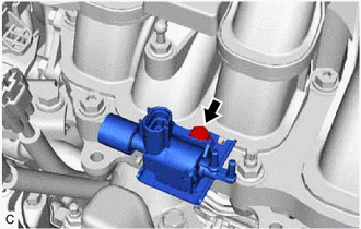
2. REMOVE NO. 1 VACUUM SWITCHING VALVE ASSEMBLY (for ACIS)
| (a) Disconnect the No. 1 vacuum switching valve assembly (for ACIS) connector. |
|
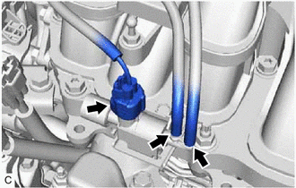
(b) Disconnect the 2 vacuum hose assemblies from the No. 1 vacuum switching valve assembly (for ACIS).
| (c) Remove the bolt and No. 1 vacuum switching valve assembly (for ACIS) from the intake air surge tank assembly. |
|
 Components
COMPONENTS ILLUSTRATION *1 NO. 1 VACUUM SWITCHING VALVE ASSEMBLY (for ACIS) *2 VACUUM HOSE SUB-ASSEMBLY *3 V-BANK COVER SUB-ASSEMBLY - - N*m (kgf*cm, ft.*lbf): Specified tor ...
 Inspection
INSPECTION PROCEDURE 1. INSPECT NO. 1 VACUUM SWITCHING VALVE ASSEMBLY (for ACIS) (a) Measure the resistance according to the value(s) in the table below. Standard Resistance: Tester Connection ...
Other materials:
Lexus RX (RX 350L, RX450h) 2016-2026 Repair Manual > Sfi System: Lack of Power
DESCRIPTION Problem Symptom Suspected Area Trouble Area
Engine speed fluctuation due to abnormal combustion
Idle speed too low or high
Strong engine vibration due to above symptoms
Ignition malfunction
Deviation in air fuel ratio (Excessive or insufficient intake air volume ...
Lexus RX (RX 350L, RX450h) 2016-2026 Repair Manual > Steering Lock System: System Description
SYSTEM DESCRIPTION UNLOCK OPERATION CONDITIONS FOR STEERING LOCK (a) When the following condition is met, the unlock operation is performed.
The engine switch is on (ACC) or on (IG). HINT: When the engine switch is turned on (ACC) or on (IG) and the key and certification ECU (smart key ECU assemb ...
Lexus RX (RX 350L, RX450h) 2016-{YEAR} Owners Manual
- For your information
- Pictorial index
- For safety and security
- Instrument cluster
- Operation of each component
- Driving
- Lexus Display Audio system
- Interior features
- Maintenance and care
- When trouble arises
- Vehicle specifications
- For owners
Lexus RX (RX 350L, RX450h) 2016-{YEAR} Repair Manual

0.009