Lexus RX (RX 350L, RX450h) 2016-2026 Repair Manual: Power Seat Position is not Memorized
DESCRIPTION
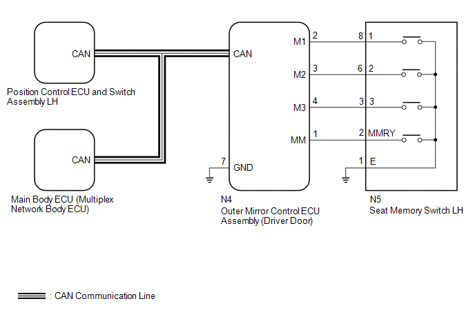
The main body ECU (multiplex network body ECU) receives seat memory switch LH signals from the outer mirror control ECU assembly via CAN communication. If the SET switch is being pressed when one of the M1, M2 or M3 switches is pressed, or if one of the M1, M2 or M3 switches is pressed within 3 seconds of pressing the SET switch, the main body ECU (multiplex network body ECU) sends a memory request signal to the position control ECU and switch assembly LH. After receiving the request signal, the position control ECU and switch assembly LH memorizes the location data of each motor.
WIRING DIAGRAM
CAUTION / NOTICE / HINT
NOTICE:
-
The seat position will not be stored if the SET switch and 2 or more of the seat memory switches (for example, M1 switch and M2 switch) are pressed simultaneously.
If a memorizing operation has failed, release all of the switches. The seat memory function will not operate unless the switches are released.
-
The seat will not return to the memorized position if 2 or more of the seat memory switches (for example, M1 switch and M2 switch) are pressed simultaneously.
If a restoring operation has failed, release all of the switches. The seat memory restoring function will not operate unless the switches are released.
-
The front power seat control system (w/ Memory) uses the CAN communication system. First, confirm that there are no malfunctions in the CAN communication system. Refer to How to Proceed with Troubleshooting.
Click here
.gif)
- Before replacing the main body ECU (multiplex network body ECU), refer to Registration.
PROCEDURE
| 1. | CHECK FRONT POWER SEAT CONTROL OPERATION |
(a) Check that each function of the power seat operates normally by using the position control ECU and switch assembly LH.
Click here
OK:
Each function of the power seat operates normally using the position control ECU and switch assembly LH.
| NG | .gif) | GO TO PROBLEM SYMPTOMS TABLE |
|
.gif)
| 2. | READ VALUE USING TECHSTREAM (SEAT MEMORY SWITCH LH) |
(a) Connect the Techstream to the DLC3.
(b) Turn the engine switch on (IG).
(c) Turn the Techstream on.
(d) Enter the following menus: Body Electrical / Mirror L / Data List.
(e) Read the Data List according to the display on the Techstream.
Body Electrical > Mirror L > Data List| Tester Display | Measurement Item | Range | Normal Condition | Diagnostic Note |
|---|---|---|---|---|
| Seat Memory Switch1 | M1 switch | ON or OFF | ON: M1 switch on OFF: M1 switch off | - |
| Seat Memory Switch2 | M2 switch | ON or OFF | ON: M2 switch on OFF: M2 switch off | - |
| Seat Memory Switch3 | M3 switch | ON or OFF | ON: M3 switch on OFF: M3 switch off | - |
| Seat Memory Set SW | SET switch | ON or OFF | ON: SET switch on OFF: SET switch off | - |
| Tester Display |
|---|
| Seat Memory Switch1 |
| Seat Memory Switch2 |
| Seat Memory Switch3 |
| Seat Memory Set SW |
OK:
On the Techstream screen, ON or OFF is displayed accordingly.
| NG | | GO TO STEP 8 |
|
| 3. | PERFORM ACTIVE TEST USING TECHSTREAM (BUZZER) |
(a) Connect the Techstream to the DLC3.
(b) Turn the engine switch on (IG).
(c) Turn the Techstream on.
(d) Enter the following menus: Body Electrical / Driver Seat / Active Test.
(e) Perform the Active Test according to the display on the Techstream.
Body Electrical > Driver Seat > Active Test| Tester Display | Measurement Item | Control Range | Diagnostic Note |
|---|---|---|---|
| Buzzer | Buzzer operation | OFF/ON | - |
| Tester Display |
|---|
| Buzzer |
OK:
Buzzer sounds normally.
| NG | | REPLACE POSITION CONTROL ECU AND SWITCH ASSEMBLY LH |
|
| 4. | REPLACE OUTER MIRROR CONTROL ECU ASSEMBLY (DRIVER DOOR) |
(a) Replace the outer mirror control ECU assembly (driver door) with a new or known good one.
Click here
|
| 5. | CHECK SEAT POSITION MEMORY AND RESTORING FUNCTION |
(a) Check the seat position memory and restoring functions.
Click here
OK:
Seat position memory and restoring functions operate normally.
| OK | | END (OUTER MIRROR CONTROL ECU ASSEMBLY (DRIVER DOOR) WAS DEFECTIVE) |
|
| 6. | REPLACE POSITION CONTROL ECU AND SWITCH ASSEMBLY LH |
(a) Replace the position control ECU and switch assembly LH with a new or known good one.
Click here
|
| 7. | CHECK SEAT POSITION MEMORY AND RESTORING FUNCTION |
(a) Check the seat position memory and restoring functions.
Click here
OK:
Seat position memory and restoring functions operate normally.
| OK | | END (POSITION CONTROL ECU AND SWITCH ASSEMBLY LH WAS DEFECTIVE) |
| NG | | REPLACE MAIN BODY ECU (MULTIPLEX NETWORK BODY ECU) |
| 8. | INSPECT SEAT MEMORY SWITCH LH |
(a) Remove the seat memory switch LH.
Click here
(b) Inspect the seat memory switch LH.
Click here
| NG | | REPLACE SEAT MEMORY SWITCH LH |
|
| 9. | CHECK HARNESS AND CONNECTOR (OUTER MIRROR CONTROL ECU ASSEMBLY (DRIVER DOOR) - SEAT MEMORY SWITCH LH - BODY GROUND) |
(a) Disconnect the N4 outer mirror control ECU assembly (driver door) connector.
(b) Measure the resistance according to the value(s) in the table below.
Standard Resistance:
| Tester Connection | Condition | Specified Condition |
|---|---|---|
| N4-1 (MM) - N5-2 (MMRY) | Always | Below 1 Ω |
| N4-1 (MM) or N5-2 (MMRY) - Body ground | Always | 10 kΩ or higher |
| N4-2 (M1) - N5-8 (1) | Always | Below 1 Ω |
| N4-2 (M1) or N5-8 (1) - Body ground | Always | 10 kΩ or higher |
| N4-3 (M2) - N5-6 (2) | Always | Below 1 Ω |
| N4-3 (M2) or N5-6 (2) - Body ground | Always | 10 kΩ or higher |
| N4-4 (M3) - N5-3 (3) | Always | Below 1 Ω |
| N4-4 (M3) or N5-3 (3) - Body ground | Always | 10 kΩ or higher |
| N4-7 (GND) - Body ground | Always | Below 1 Ω |
| N5-1 (E) - Body ground | Always | Below 1 Ω |
| OK | | REPLACE OUTER MIRROR CONTROL ECU ASSEMBLY (DRIVER DOOR) |
| NG | | REPAIR OR REPLACE HARNESS OR CONNECTOR |
 One or more Power Seat Motors do not Operate
DESCRIPTION Signals are input into the position control ECU and switch assembly LH. The built-in ECU manages the signals received from the position control ECU and switch assembly LH, and operates eac ...
 Power Seat does not Return to Memorized Position
DESCRIPTION When the M1, M2 or M3 switch of the seat memory switch LH is pressed, the outer mirror control ECU assembly sends a switch signal to the main body ECU (multiplex network body ECU) via CAN ...
Other materials:
Lexus RX (RX 350L, RX450h) 2016-2026 Repair Manual > Lighting System (w/ Automatic Headlight Beam Level Control System): Parking Light/Daytime Running Light Circuit
DESCRIPTION Parking light function:
When the main body ECU (multiplex network body ECU) receives the light control switch position signal, it sends an illumination request signal to the No. 1 headlight ECU sub-assembly and illuminates the parking lights.
Daytime running light function:
When ...
Lexus RX (RX 350L, RX450h) 2016-2026 Repair Manual > Shift Lever: Reassembly
REASSEMBLY PROCEDURE 1. INSTALL SHIFT POSITION INDICATOR (a) Install the shift position indicator and console box bracket to the upper console panel sub-assembly with the 2 screws. *1 Console Box Bracket *2 Shift Position Indicator 2. INSTALL ELECTRIC PARKING BRAKE S ...
Lexus RX (RX 350L, RX450h) 2016-{YEAR} Owners Manual
- For your information
- Pictorial index
- For safety and security
- Instrument cluster
- Operation of each component
- Driving
- Lexus Display Audio system
- Interior features
- Maintenance and care
- When trouble arises
- Vehicle specifications
- For owners
Lexus RX (RX 350L, RX450h) 2016-{YEAR} Repair Manual

0.0121