Lexus RX (RX 350L, RX450h) 2016-2026 Repair Manual: One or more Power Seat Motors do not Operate
DESCRIPTION
Signals are input into the position control ECU and switch assembly LH. The built-in ECU manages the signals received from the position control ECU and switch assembly LH, and operates each motor. If the position control ECU and switch assembly LH receives more than 2 motor operation signals for the same motor, the motor will be stopped. Manual operation is restarted when the position control ECU and switch assembly LH receives 1 signal only.
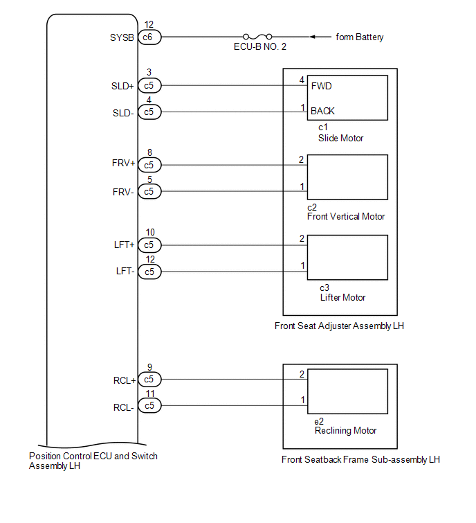
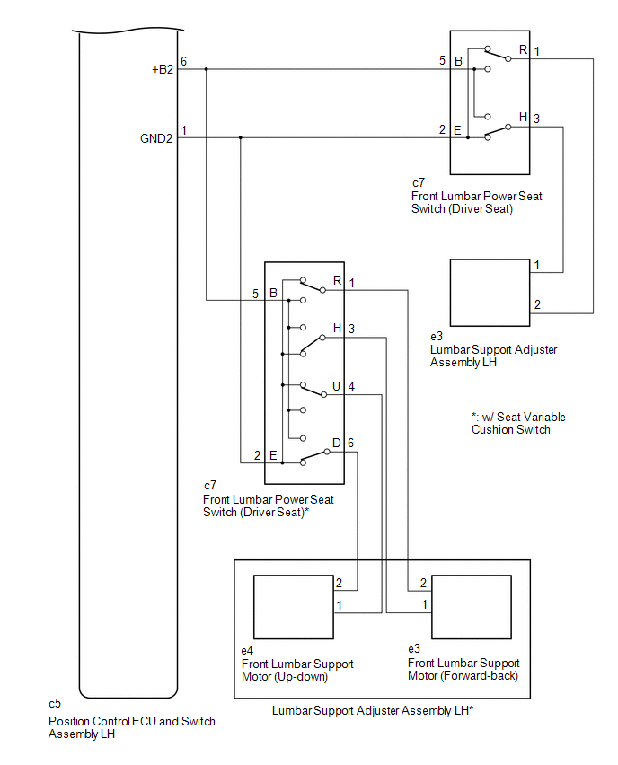
WIRING DIAGRAM
CAUTION / NOTICE / HINT
NOTICE:
Inspect the fuses for circuits related to this system before performing the following procedure.
PROCEDURE
| 1. | CHECK FRONT POWER SEAT OPERATION |
(a) Check that each function of the power seat operates normally by using the position control ECU and switch assembly LH.
Click here .gif)
| Result | Proceed to |
|---|---|
| One or more power seat functions (except lumbar support adjustment function) do not operate | A |
| All power seat functions do not operate | B |
| Front vertical and lifter functions do not operate | C |
| Only lumbar support adjustment function does not operate | D |
| B | .gif) | GO TO OTHER DIAGNOSIS PROCEDURE (Front Power Seat does not Operate with Front Power Seat Switch) |
| C | | GO TO STEP 7 |
| D | | GO TO STEP 8 |
|
.gif)
| 2. | READ VALUE USING TECHSTREAM (POWER SEAT SWITCH) |
(a) Connect the Techstream to the DLC3.
(b) Turn the engine switch on (IG).
(c) Turn the Techstream on.
(d) Enter the following menus: Body Electrical / Driver Seat / Data List.
(e) Read the Data List according to the display on the Techstream.
Body Electrical > Driver Seat > Data List| Tester Display | Measurement Item | Range | Normal Condition | Diagnostic Note |
|---|---|---|---|---|
| Reclining Rear | Reclining switch signal (Rearward) | ON or OFF | ON: Reclining switch (Rearward) on OFF: Reclining switch (Rearward) off | - |
| Reclining Front | Reclining switch signal (Forward) | ON or OFF | ON: Reclining switch (Forward) on OFF: Reclining switch (Forward) off | - |
| Front Vertical Down | Front vertical switch signal (Downward) | ON or OFF | ON: Front vertical switch (Downward) on OFF: Front vertical switch (Downward) off | - |
| Front Vertical Up | Front vertical switch signal (Upward) | ON or OFF | ON: Front vertical switch (Upward) on OFF: Front vertical switch (Upward) off | - |
| Lifter Switch Down | Lifter switch signal (Downward) | ON or OFF | ON: Lifter switch (Downward) on OFF: Lifter switch (Downward) off | - |
| Lifter Switch Up | Lifter switch signal (Upward) | ON or OFF | ON: Lifter switch (Upward) on OFF: Lifter switch (Upward) off | - |
| Slide Rear | Slide switch signal (Rearward) | ON or OFF | ON: Slide switch (Rearward) on OFF: Slide switch (Rearward) off | - |
| Slide Front | Slide switch signal (Forward) | ON or OFF | ON: Slide switch (Forward) on OFF: Slide switch (Forward) off | - |
| Tester Display |
|---|
| Reclining Rear |
| Reclining Front |
| Front Vertical Down |
| Front Vertical Up |
| Lifter Switch Down |
| Lifter Switch Up |
| Slide Rear |
| Slide Front |
OK:
On the Techstream screen, ON or OFF is displayed accordingly
| NG | | GO TO STEP 6 |
|
| 3. | PERFORM ACTIVE TEST USING TECHSTREAM (POWER SEAT MOTOR) |
(a) Enter the following menus: Body Electrical / Driver Seat / Active Test.
(b) Perform the Active Test according to the display on the Techstream.
Body Electrical > Driver Seat > Active Test| Tester Display | Measurement Item | Control Range | Diagnostic Note |
|---|---|---|---|
| Seat Reclining | Seat reclining operation | OFF/Rear/Front | - |
| Front Vertical Operation | Seat front vertical operation | OFF/Down/Up | - |
| Lifter Operation | Seat lifter operation | OFF/Down/Up | - |
| Seat Slide Operation | Seat slide operation | OFF/Rear/Front | - |
| Tester Display |
|---|
| Seat Reclining |
| Tester Display |
|---|
| Front Vertical Operation |
| Tester Display |
|---|
| Lifter Operation |
| Tester Display |
|---|
| Seat Slide Operation |
| Result | Proceed to |
|---|---|
| The power seat functions operate normally. | A |
| Slide, front vertical or lifter function does not operate normally. | B |
| Reclining function does not operate normally. | C |
| A | | REPLACE POSITION CONTROL ECU AND SWITCH ASSEMBLY LH |
| C | | GO TO STEP 5 |
|
| 4. | INSPECT FRONT SEAT ADJUSTER ASSEMBLY LH |
HINT:
Check the operation of the motor of the function that did not operate normally.
(a) Remove the front seat adjuster assembly LH.
Click here
(b) Inspect the front seat adjuster assembly LH (slide motor, front vertical motor or lifter motor).
Click here
| OK | | GO TO STEP 6 |
| NG | | REPLACE FRONT SEAT ADJUSTER ASSEMBLY LH |
| 5. | INSPECT FRONT SEATBACK FRAME SUB-ASSEMBLY LH |
(a) Remove the front seatback frame sub-assembly LH.
Click here
(b) Inspect the front seatback frame sub-assembly LH (reclining motor).
Click here
| NG | | REPLACE FRONT SEATBACK FRAME SUB-ASSEMBLY LH |
|
| 6. | CHECK HARNESS AND CONNECTOR (POSITION CONTROL ECU AND SWITCH ASSEMBLY LH - POWER SEAT MOTOR) |
(a) Disconnect the c5 position control ECU and switch assembly LH connector.
(b) Measure the resistance according to the value(s) in the table below.
HINT:
Check the wire harness and connector between the position control ECU and switch assembly LH and applicable motor.
Standard Resistance:
| Tester Connection | Condition | Specified Condition |
|---|---|---|
| c5-3 (SLD+) - c1-4 | Always | Below 1 Ω |
| c5-3 (SLD+) or c1-4 - Body ground | Always | 10 kΩ or higher |
| c5-4 (SLD-) - c1-1 | Always | Below 1 Ω |
| c5-4 (SLD-) or c1-1 - Body ground | Always | 10 kΩ or higher |
| c5-5 (FRV-) - c2-1 | Always | Below 1 Ω |
| c5-5 (FRV-) or c2-1 - Body ground | Always | 10 kΩ or higher |
| c5-8 (FRV+) - c2-2 | Always | Below 1 Ω |
| c5-8 (FRV+) or c2-2 - Body ground | Always | 10 kΩ or higher |
| c5-10 (LFT+) - c3-2 | Always | Below 1 Ω |
| c5-10 (LFT+) or c3-2 - Body ground | Always | 10 kΩ or higher |
| c5-12 (LFT-) - c3-1 | Always | Below 1 Ω |
| c5-12 (LFT-) or c3-1 - Body ground | Always | 10 kΩ or higher |
| c5-9 (RCL+) - e2-2 | Always | Below 1 Ω |
| c5-9 (RCL+) or e2-2 - Body ground | Always | 10 kΩ or higher |
| c5-11 (RCL-) - e2-1 | Always | Below 1 Ω |
| c5-11 (RCL-) or e2-1 - Body ground | Always | 10 kΩ or higher |
| OK | | REPLACE POSITION CONTROL ECU AND SWITCH ASSEMBLY LH |
| NG | | REPAIR OR REPLACE HARNESS OR CONNECTOR |
| 7. | CHECK HARNESS AND CONNECTOR (POSITION CONTROL ECU AND SWITCH ASSEMBLY LH - BATTERY) |
(a) Disconnect the c6 position control ECU and switch assembly LH connector.
(b) Measure the voltage according to the value(s) in the table below.
Standard Voltage:
| Tester Connection | Condition | Specified Condition |
|---|---|---|
| c6-12 (SYSB) - Body ground | Always | 11 to 14 V |
| OK | | REPLACE POSITION CONTROL ECU AND SWITCH ASSEMBLY LH |
| NG | | REPAIR OR REPLACE HARNESS OR CONNECTOR |
| 8. | INSPECT FRONT LUMBAR POWER SEAT SWITCH (DRIVER SEAT) |
(a) Remove the front lumbar power seat switch (driver seat).
Click here
(b) Inspect the front lumbar power seat switch (driver seat).
Click here
| NG | | REPLACE FRONT LUMBAR POWER SEAT SWITCH (DRIVER SEAT) |
|
| 9. | INSPECT LUMBAR SUPPORT ADJUSTER ASSEMBLY LH |
(a) Remove the lumbar support adjuster assembly LH.
Click here
(b) Inspect the lumbar support adjuster assembly LH.
Click here
| NG | | REPLACE LUMBAR SUPPORT ADJUSTER ASSEMBLY LH |
|
| 10. | CHECK HARNESS AND CONNECTOR (POSITION CONTROL ECU AND SWITCH ASSEMBLY LH - FRONT LUMBAR POWER SEAT SWITCH (DRIVER SEAT)) |
(a) Disconnect the c5 position control ECU and switch assembly LH connector.
(b) Measure the resistance according to the value(s) in the table below.
Standard Resistance:
| Tester Connection | Condition | Specified Condition |
|---|---|---|
| c5-6 (+B2) - c7-5 (B) | Always | Below 1 Ω |
| c5-6 (+B2) or c7-5 (B) - Body ground | Always | 10 kΩ or higher |
| c5-1 (GND2) - c7-2 (E) | Always | Below 1 Ω |
| c5-1 (GND2) or c7-2 (E) - Body ground | Always | 10 kΩ or higher |
| NG | | REPAIR OR REPLACE HARNESS OR CONNECTOR |
|
| 11. | CHECK HARNESS AND CONNECTOR (FRONT LUMBAR POWER SEAT SWITCH (DRIVER SEAT) - LUMBAR SUPPORT ADJUSTER ASSEMBLY LH) |
(a) Measure the resistance according to the value(s) in the table below.
Standard Resistance:
| Tester Connection | Condition | Specified Condition |
|---|---|---|
| c7-3 (H) - e3-1 | Always | Below 1 Ω |
| c7-3 (H) or e3-1 - Body ground | Always | 10 kΩ or higher |
| c7-1 (R) - e3-2 | Always | Below 1 Ω |
| c7-1 (R) or e3-2 - Body ground | Always | 10 kΩ or higher |
| c7-3 (H) - e3-1* | Always | Below 1 Ω |
| c7-3 (H) or e3-1 - Body ground* | Always | 10 kΩ or higher |
| c7-1 (R) - e3-2* | Always | Below 1 Ω |
| c7-1 (R) or e3-2 - Body ground* | Always | 10 kΩ or higher |
| c7-4 (U) - e4-1* | Always | Below 1 Ω |
| c7-4 (U) or e4-1 - Body ground* | Always | 10 kΩ or higher |
| c7-6 (D) - e4-2* | Always | Below 1 Ω |
| c7-6 (D) or e4-2 - Body ground* | Always | 10 kΩ or higher |
- *: w/ Seat Variable Cushion Switch
| OK | | REPLACE POSITION CONTROL ECU AND SWITCH ASSEMBLY LH |
| NG | | REPAIR OR REPLACE HARNESS OR CONNECTOR |
 Front Power Seat does not Operate with Front Power Seat Switch
DESCRIPTION Signals are input into the position control ECU and switch assembly LH. The built-in ECU manages the signals received from the power seat switch, and operates each motor. If the position c ...
 Power Seat Position is not Memorized
DESCRIPTION The main body ECU (multiplex network body ECU) receives seat memory switch LH signals from the outer mirror control ECU assembly via CAN communication. If the SET switch is being pressed w ...
Other materials:
Lexus RX (RX 350L, RX450h) 2016-2026 Repair Manual > Smart Access System With Push-button Start (for Start Function): System Diagram
SYSTEM DIAGRAM Component Outline Engine switch
Transponder key amplifier
Turns on the power and starts the engine.
Contains a built-in transponder key amplifier to start the engine when the electrical key transmitter sub-assembly does not operate properly due to a depleted ...
Lexus RX (RX 350L, RX450h) 2016-2026 Repair Manual > Rear Center Seat Inner Belt Assembly(w/ Rear No. 2 Seat): Installation
INSTALLATION PROCEDURE 1. INSTALL REAR CENTER SEAT INNER BELT ASSEMBLY (a) Install the rear center seat inner belt assembly with the bolt. Torque: 42 N·m {428 kgf·cm, 31 ft·lbf} NOTICE: Do not allow the anchor part of the rear center seat inner belt assembly to overlap the protruding parts of th ...
Lexus RX (RX 350L, RX450h) 2016-{YEAR} Owners Manual
- For your information
- Pictorial index
- For safety and security
- Instrument cluster
- Operation of each component
- Driving
- Lexus Display Audio system
- Interior features
- Maintenance and care
- When trouble arises
- Vehicle specifications
- For owners
Lexus RX (RX 350L, RX450h) 2016-{YEAR} Repair Manual

0.0098