Lexus RX (RX 350L, RX450h) 2016-2026 Repair Manual: Removal
REMOVAL
CAUTION / NOTICE / HINT
The necessary procedures (adjustment, calibration, initialization or registration) that must be performed after parts are removed and installed, or replaced during electrical key and tire pressure warning ECU and receiver removal/installation are shown below.
Necessary Procedures after parts removed/installed/replaced| Replaced Part or Performed Procedure | Necessary Procedure | Effect/Inoperative Function when Necessary Procedure not Performed | Link |
|---|---|---|---|
|
*1: When performing learning using the Techstream.
Click here | |||
| Disconnect cable from negative battery terminal | Memorize steering angle neutral point | Lane Control System | |
| Pre-collision System | |||
| Intelligent Clearance Sonar System*1 | |||
| Lighting System (w/ Automatic Headlight Beam Level Control System) | | ||
| Parking Assist Monitor System | | ||
| Panoramic View Monitor System | | ||
| Initialize back door lock | Power Door Lock Control System | | |
| Reset back door close position | Power Back Door System (w/ Outside Door Control Switch) | | |
| Electrical key and tire pressure warning ECU and receiver |
|
| |
NOTICE:
When replacing the electrical key and tire pressure warning ECU and receiver, read the transmitter IDs stored in the old ECU using the Techstream and write them down before removal.
Click here .gif)
PROCEDURE
1. REMOVE TONNEAU COVER ASSEMBLY (w/o Rear No. 2 Seat)
Click here
2. REMOVE DECK BOARD ASSEMBLY (w/o Rear No. 2 Seat)
Click here
3. REMOVE REAR NO. 3 FLOOR BOARD (w/o Rear No. 2 Seat)
Click here
4. REMOVE REAR DECK FLOOR BOX (w/o Rear No. 2 Seat)
Click here
5. REMOVE REAR NO. 4 FLOOR BOARD (w/o Rear No. 2 Seat)
Click here
6. REMOVE DECK SIDE TRIM BOX RH (w/o Rear No. 2 Seat)
Click here
7. REMOVE REAR FLOOR FINISH PLATE (w/o Rear No. 2 Seat)
Click here
8. REMOVE REAR DOOR SCUFF PLATE RH (w/o Rear No. 2 Seat)
HINT:
Use the same procedure as for the LH side.
Click here
9. REMOVE REAR SEAT ASSEMBLY RH (w/o Rear No. 2 Seat)
Click here
10. REMOVE UPPER QUARTER TRIM PAD RH (w/o Rear No. 2 Seat)
HINT:
Use the same procedure as for the LH side.
Click here
11. REMOVE REAR SEAT SIDE GARNISH RH (w/o Rear No. 2 Seat)
HINT:
Use the same procedure as for the LH side.
Click here
12. REMOVE REAR FLOOR FINISH SIDE PLATE RH (w/o Rear No. 2 Seat)
HINT:
Use the same procedure as for the LH side.
Click here
13. REMOVE NO. 1 LUGGAGE COMPARTMENT TRIM HOOK (w/o Rear No. 2 Seat)
Click here
14. REMOVE ROPE HOOK ASSEMBLY (w/o Rear No. 2 Seat)
HINT:
Use the same procedure as for the LH side.
Click here
15. REMOVE NO. 1 LUGGAGE COMPARTMENT LIGHT ASSEMBLY (w/o Rear No. 2 Seat)
Click here
16. REMOVE RECLINING REMOTE CONTROL BEZEL RH (w/o Rear No. 2 Seat)
w/o Rear Power Seat System:
Click here
17. REMOVE FOLD SEAT SWITCH ASSEMBLY (w/o Rear No. 2 Seat)
w/ Rear Power Seat System:
Click here
18. REMOVE DECK TRIM SIDE PANEL ASSEMBLY RH (w/o Rear No. 2 Seat)
Click here
19. REMOVE ROOF SIDE INNER GARNISH ASSEMBLY RH (w/o Rear No. 2 Seat)
HINT:
Use the same procedure as for the LH side.
Click here
20. REMOVE REAR NO. 2 SEAT ASSEMBLY (w/ Rear No. 2 Seat)
Click here
21. REMOVE REAR DOOR SCUFF PLATE RH (w/ Rear No. 2 Seat)
HINT:
Use the same procedure as for the LH side.
Click here
22. REMOVE REAR DOOR INSIDE SCUFF PLATE RH (w/ Rear No. 2 Seat)
HINT:
Use the same procedure as for the LH side.
Click here
23. REMOVE REAR SEAT OUTER TRACK BRACKET COVER RH (w/ Rear No. 2 Seat)
for 60/40 Split Seat Type:
Click here
for Captain Seat Type:
HINT:
Use the same procedure as for the LH side.
Click here
24. REMOVE FRONT DECK SIDE TRIM COVER RH (w/ Rear No. 2 Seat)
HINT:
Use the same procedure as for the LH side.
Click here
25. REMOVE REAR SEAT SIDE GARNISH RH (w/ Rear No. 2 Seat)
Click here
26. REMOVE NO. 1 LUGGAGE COMPARTMENT TRIM HOOK (w/ Rear No. 2 Seat)
Click here
27. REMOVE ROPE HOOK ASSEMBLY (w/ Rear No. 2 Seat)
HINT:
Use the same procedure as for the LH side.
Click here
28. REMOVE NO. 1 LUGGAGE COMPARTMENT LIGHT ASSEMBLY (w/ Rear No. 2 Seat)
Click here
29. REMOVE DECK TRIM SIDE PANEL ASSEMBLY RH (w/ Rear No. 2 Seat)
Click here
30. DISCONNECT REAR NO. 2 SEAT OUTER BELT ASSEMBLY RH (w/ Rear No. 2 Seat)
HINT:
Use the same procedure as for the LH side.
Click here
31. REMOVE ROOF SIDE INNER GARNISH ASSEMBLY RH (w/ Rear No. 2 Seat)
HINT:
Use the same procedure as for the LH side.
Click here
32. REMOVE ELECTRICAL KEY AND TIRE PRESSURE WARNING ECU AND RECEIVER
NOTICE:
- Do not drop the electrical key and tire pressure warning ECU and receiver, strike it with tools or subject it to impact.
- If the electrical key and tire pressure warning ECU and receiver is subjected to an impact, replace it with a new one.
| (a) Remove the bolt. |
|
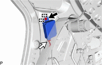
(b) Disengage the 2 guides.
(c) Disconnect the connector to remove the electrical key and tire pressure warning ECU and receiver.
 Components
COMPONENTS ILLUSTRATION *A w/o Rear No. 2 Seat *B for TMC Made *C for TMMC Made - - *1 DECK BOARD ASSEMBLY *2 DECK SIDE TRIM BOX RH *3 REAR DECK FLOOR BOX *4 RE ...
 Installation
INSTALLATION PROCEDURE 1. INSTALL ELECTRICAL KEY AND TIRE PRESSURE WARNING ECU AND RECEIVER NOTICE:
Do not drop the electrical key and tire pressure warning ECU and receiver, strike it with tools o ...
Other materials:
Lexus RX (RX 350L, RX450h) 2016-2026 Repair Manual > Intelligent Clearance Sonar System: Wheel Speed Sensor Malfunction (C164D)
DESCRIPTION This DTC is stored when the clearance warning ECU assembly receives a wheel speed sensor (front speed sensor RH or front speed sensor LH, rear speed sensor RH or rear speed sensor LH) abnormality signal from the vehicle stability control system via CAN communication. DTC No. Detecti ...
Lexus RX (RX 350L, RX450h) 2016-2026 Repair Manual > Rear Wiper Rubber: Components
COMPONENTS ILLUSTRATION *A w/o Rear No. 2 Seat - - *1 REAR WIPER BLADE *2 REAR WIPER RUBBER *3 REAR WIPER RUBBER BACKING PLATE - - ILLUSTRATION *A w/ Rear No. 2 Seat - - *1 REAR WIPER BLADE *2 REAR WIPER RUBBER *3 REAR WIPER RUBBER BACKING P ...
Lexus RX (RX 350L, RX450h) 2016-{YEAR} Owners Manual
- For your information
- Pictorial index
- For safety and security
- Instrument cluster
- Operation of each component
- Driving
- Lexus Display Audio system
- Interior features
- Maintenance and care
- When trouble arises
- Vehicle specifications
- For owners
Lexus RX (RX 350L, RX450h) 2016-{YEAR} Repair Manual

0.0098