Lexus RX (RX 350L, RX450h) 2016-2026 Repair Manual: Front Power Seat does not Operate with Front Power Seat Switch
DESCRIPTION
Signals are input into the position control ECU and switch assembly LH. The built-in ECU manages the signals received from the power seat switch, and operates each motor. If the position control ECU and switch assembly LH receives more than 2 motor operation signals for the same motor, the motor will be stopped. Manual operation is restarted when the position control ECU and switch assembly LH receives 1 signal only.
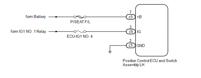
WIRING DIAGRAM
CAUTION / NOTICE / HINT
NOTICE:
Inspect the fuses for circuits related to this system before performing the following procedure.
PROCEDURE
| 1. | CHECK FRONT POWER SEAT OPERATION |
(a) Check that each function of the power seat operates normally by using the position control ECU and switch assembly LH.
Click here .gif)
| Result | Proceed to |
|---|---|
| All power seat functions do not operate | A |
| One or more power seat functions do not operate | B |
| B | .gif) | GO TO OTHER DIAGNOSIS PROCEDURE (One or more Power Seat Motors do not Operate) |
|
.gif)
| 2. | CHECK HARNESS AND CONNECTOR (POSITION CONTROL ECU AND SWITCH ASSEMBLY LH - POWER SUPPLY) |
(a) Disconnect the c5 and c6 position control ECU and switch assembly LH connectors.
(b) Measure the voltage according to the value(s) in the table below.
Standard Voltage:
| Tester Connection | Condition | Specified Condition |
|---|---|---|
| c5-7 (+B) - Body ground | Always | 11 to 14 V |
| c6-3 (IG) - Body ground | Engine switch on (IG) | 11 to 14 V |
| c6-3 (IG) - Body ground | Engine switch off | Below 1 V |
| NG | | REPAIR OR REPLACE HARNESS OR CONNECTOR |
|
| 3. | CHECK HARNESS AND CONNECTOR (POSITION CONTROL ECU AND SWITCH ASSEMBLY LH - BODY GROUND) |
(a) Measure the resistance according to the value(s) in the table below.
Standard Resistance:
| Tester Connection | Condition | Specified Condition |
|---|---|---|
| c5-2 (GND) - Body ground | Always | Below 1 Ω |
| OK | | REPLACE POSITION CONTROL ECU AND SWITCH ASSEMBLY LH |
| NG | | REPAIR OR REPLACE HARNESS OR CONNECTOR |
 Short in Sensor with Motor Power Supply Circuit (B2658)
DESCRIPTION This DTC is stored when the slide motor is being operated (the slide motor position sensor is being supplied with power) and the power supply voltage does not rise to the specified value. ...
 One or more Power Seat Motors do not Operate
DESCRIPTION Signals are input into the position control ECU and switch assembly LH. The built-in ECU manages the signals received from the position control ECU and switch assembly LH, and operates eac ...
Other materials:
Lexus RX (RX 350L, RX450h) 2016-2026 Repair Manual > Intuitive Parking Assist System (w/ Intelligent Clearance Sonar System): Rear Left Center Sensor Malfunction (C1AE7)
DESCRIPTION The rear center ultrasonic sensor LH is installed to the rear bumper. The clearance warning ECU assembly detects obstacles based on signals received from the rear center ultrasonic sensor LH. If the rear center ultrasonic sensor LH has an open circuit or other malfunction, it will not fu ...
Lexus RX (RX 350L, RX450h) 2016-2026 Repair Manual > Certification Ecu: Installation
INSTALLATION CAUTION / NOTICE / HINT NOTICE: Before replacing the certification ECU (smart key ECU assembly), refer to Registration. Click here PROCEDURE 1. INSTALL CERTIFICATION ECU (SMART KEY ECU ASSEMBLY) (a) Engage the 2 claws to install the certification ECU (smart key ECU assembly) as show ...
Lexus RX (RX 350L, RX450h) 2016-{YEAR} Owners Manual
- For your information
- Pictorial index
- For safety and security
- Instrument cluster
- Operation of each component
- Driving
- Lexus Display Audio system
- Interior features
- Maintenance and care
- When trouble arises
- Vehicle specifications
- For owners
Lexus RX (RX 350L, RX450h) 2016-{YEAR} Repair Manual

0.0133